background image

— 33 —

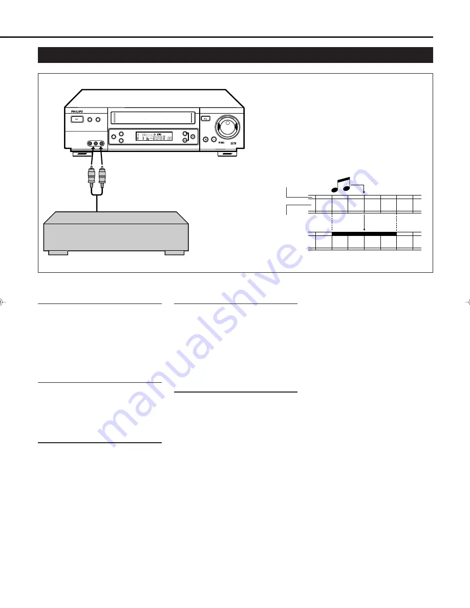
Audio Dubbing

Pre-recorded tape

Audio-dubbed tape

Normal audio track

Audio dubbing replaces the normal audio sound of a
previously recorded tape with a new soundtrack. Use your
VCR as the recorder.

Video/Hi-Fi audio
track

1

Make Connections

Connect an audio component to the
AUDIO IN (L and R) connectors on the
VCR’s front panel.
• When using monaural equipment,

use only VCR’s AUDIO IN L
connector.

2

Set Input Mode

Press 

Number

 button “0” and or

PROG.

 +/– on the remote control to

select “F-1” or “S-1” on the display
window.

3

Locate Start Point

Press 

PLAY


3 to start playback of the

tape in the VCR, and press 

PAUSE/

STILL


8 when you find a point where

you want to start dubbing. Press

AUDIO DUBBING

 on the front panel.

• Your VCR enters the Audio Dubbing

Pause mode. 

‡ (REC) blinks,

#* (PLAY and PAUSE) lights up on
the display window.

4

Start Dubbing

Engage the audio component’s PLAY
mode, then press PLAY 

3 to start the

tape in your VCR. Audio Dubbing
begins at this point.
• To stop dubbing temporarily, press

PAUSE/STILL


8. To resume

dubbing, press PLAY 

3.

5

End Audio Dubbing

Press 

STOP


7 to stop the tape in the

VCR, and engage the audio
component’s stop mode.

Note:
• When monitoring the sound during

Audio Dubbing, the normal sound-
track is automatically selected. If you
wish to hear the mixed sound (Hi-Fi
+ Normal soundtracks), press

AUDIO

 on the remote control and

select the soundtrack you wish to
hear.

• Audio dubbing stops automatically

when the counter reaches “0:00:00”,
and the recorder enters the Play
mode. Check the counter reading
before dubbing.

• Audio dubbing is also possible using

the rear panel AV1 IN/OUT or AV2
IN/DECODER connector. When
using this connector, make sure to
select the correct input mode in step
2.

• Audio dubbing cannot be performed

on a cassette that has had its record
safety tab removed.

• When playing back an audio-dubbed

tape, press 

AUDIO 

on the remote

control to select the soundtrack you
wish to hear. (

P.25)

SUPER VHS 

@

FO

RW

A

R

D

R

E

W

IN

D

RECORD

     DISPLAY

AUDIO DUBBING

REC LINK

SPEED

POWER

DIGITAL TBC/NR

VR 1000  VIDEO CASSETTE RECORDER

PROGRAMME

PLAY

PAUSE/STILL

STOP/EJECT

+8

4

0

6

-15dB

NORM

1

2

SP SLP

VCR


TIME BASE CORRECTOR  DIGITAL NOISE REDUCTION  SMARTPICTURE 

/

625

VPS/PDC

REVIEW

+

VIDEO

L  AUDIO  R

Audio component

(CD player etc.)

Audio cable

VR1000/07-New

99.7.8, 3:34 PM

33

Summary of Contents for VR1000/02X

Page 1: ...the rear of the unit Table of Contents Some Do s and Dont s 3 Description of Controls 4 Front Panel 4 Rear Panel 5 On Screen Display 5 Remote Control 6 Display Window 8 Getting Connected Up 9 VCR to TV Connection using the RF Connection 9 VCR to AV TV Connection using the SCART Connection 9 VCR to AV TV Connection using the S video Connection 10 Setting Up 11 Auto Set Up Preset Download 11 Setting...

Page 2: ...t it working normally or if it is damaged in any way switch off withdraw the mains plug and consult your dealer DON T remove any fixed cover as this may expose dangerous voltages DON T leave equipment switched on when it is unattended unless it is specifically stated that it is designed for unattended operation or has a standby mode Switch off using the switch on the equipment and make sure that y...

Page 3: ...The lamp the button itself will light P 28 3 DIGITAL TBC NR button Removes jitter from fluctuating video to deliver a stable picture The lamp the button itself will light P 25 4 SPEED button Selects the tape speed for recording SP LP During playback the tape speed is automatically selected SP LP or EP for NTSC signal only P 22 P 29 P 30 SP LP For PAL signal SP EP For NTSC signal 5 DISPLAY button S...

Page 4: ...ctor 9 RF OUT output terminal to TV Use the supplied RF coaxial cable to connect this terminal to the UHF VHF input terminal on the TV P 9 3 AV1 OUT switch Selects the type of signal output via the 21 pin AV1 IN OUT connector P 9 4 AV1 IN OUT Connector SCART For connecting to the AV terminal on TV or another VCR P 9 P 32 1 Operation mode 2 Cassette In Indicator 3 SmartPicture setting or Timer warn...

Page 5: ...ng playback P 23 11 SMARTPICTURE button Selects the SmartPicture mode P 24 12 MENU button Calls up the main menu 13 JOG SHTL Shuttle button and lamp Activates the jog dial and shuttle ring on the remote control when the lamp the button itself is lit P 23 14 Shuttle ring Starts reverse or forward rapid visual search during playback or still picture mode P 23 15 TV POWER button Turns the TV on or of...

Page 6: ...n using the menus 28 RECORD button Starts recording when pressed once P 22 Starts a recording for 30 minutes to 6 hours long When pressed more than once the shut off time increases in 30 minute intervals P 26 CAUTION On Battery Replacement Do not mix old and new batteries Also never mix alkaline batteries with manganese batteries Note This remote control and batteries are supplied accessories Chec...

Page 7: ...le recording on an S VHS tape using S VHS format 10 VCR indicator Lights up when the VCR TV button is pressed or when playback is started or when scrambled broadcast is received 11 PDC indicator Lights up when PDC is engaged for timer recording or when PDC signal is received VPS Video Programme System is not currently available in the U K and not possible with this VCR 12 Digital clock counter Cha...

Page 8: ...ting gives you high quality S VHS pictures GETTING CONNECTED UP VCR to TV Connection using the RF connection To connect to a TV with No 21 pin AV input connector 1 Disconnect the antenna or cable from the TV and the AC power cord of the TV from the AC outlet 2 Connect the antenna or cable to the VCR 3 Connect the VCR to the TV using the RF coaxial cable 4 Plug the AC power cords of the VCR and TV ...

Page 9: ...s After you plug the AC power cord into an AC outlet the Auto Set up Preset Download display appears on the TV screen and on the VCR s display window when the STANDBY ON or VCR POWER button is pressed for the first time to power on the VCR Go to the next page to perform Auto Set Up or Preset Download If you are using a Decoder and or Satellite Tuner see page 34 and 35 also From antenna S Video Cab...

Page 10: ...ow If you use Preset Download function go to Preset Download on page 13 SETTING UP Auto Set Up Before performing the following steps be sure to finish Preparation above Do NOT press any button on the front panel or remote control until display window shows either the display as illustrated in step 2 or 2 If you have connected the VCR to TV via an RF cable only RF connection the channel that is sho...

Page 11: ...rd is selected P 29 7 Your VCR memorizes all detected stations even if reception of some of them is poor In these cases picture quality may be poor To delete those stations with an unacceptable picture see page 16 7 For RF connection users In certain reception conditions the Video Channel may not be set correctly and interference may appear in the TV picture while the VCR s power is on Set your Vi...

Page 12: ... at the top left corner of the screen for about 5 seconds when the VCR is tuned to a different station If you want to set the tuner manually such as to add or skip channels to change channel positions or to set station names see pages 16 17 If no station is stored in the VCR s memory make sure the SCART cable is connected correctly and press OK to re perform Preset Download Notes In the area where...

Page 13: ...2 Turn on the TV and tune it to any UHF channel between 22 and 69 you want to use as the video channel on the TV Select a channel not used in your area 3 Press STOP EJECT 7 0 on the front panel for more than 5 seconds The following indication appears on the display 4 Press PROGRAMME or PROG to select the channel you have tuned on the TV as the video channel in step 2 A test signal two vertical whi...

Page 14: ...ain for your new residential area 1Perform Auto Channel Set 1 Press MENU 2 Press 5or to select AUTO CH SET then press OK or 4 3 Press 5or to select AUTO SET then press OK or 4 The Auto Set screen appears as below 2Confirm Programmed Channel Information List Once it is completed COMPLETED is displayed on the screen for about 5 seconds The following screen will appear after 5 seconds or if you press...

Page 15: ... The item directly beneath the cancelled one moves up one line 5 Press MENU to exit from the menu operations If you want to change the channel positions You can also replace the channel position numbers 1 Press MENU 2 Press 5or to select MANUAL CH SET then press OK or 3 3 Press 5or until the item you want to change begins blinking then press OK 4 Press 5or to move the station to the new channel po...

Page 16: ...s clearest 5 Press OK The programmed channel list appears 6 Press MENU to exit the menu operations If you want to change station names You can also change the station name manually 1 Press MENU 2 Press to select MANUAL CH SET then press OK or 3 3 Press 5 23until the item you want begins blinking 4 Press OK twice The Manual Channel Set screen appears 5 If you want to change the station name to regi...

Page 17: ...7 RAI1 RAI1 RAI2 RAI2 RAI3 RAI3 RB1 RB1 RB3 RB3 Rikisutvarpid S RKPS RTBF 1 RTB1 RTBF 2 RTB2 RTE 1 RTE1 RTL RTL RTL 2 RTL2 RTP RTP STATION NAME ID SAT SAT SAT 1 SAT1 Scottish TV SCOT SC4 SC4 SDR SDR SDR1 SDR1 SFB1 SFB1 SFB3 SFB3 SKY SKY Sky One SKY1 Sky Net SKYN Sport SPRT SR 1 SR1 Super RTL SRTL STV Test STVT STV 1 STV1 STV 2 STV2 Suedwest3 SWR SWF 1 SWF1 Schweiz4 SWZ4 TYNE TEES TEES Text TEXT TF...

Page 18: ...ds Ridge Hill 22 28 25 32 35 Sutton Coldfield 46 40 43 50 37 The Wrekin 26 33 23 29 35 Waltham 58 64 61 54 35 North Belmont 22 28 25 32 56 Emley Moor 44 51 47 41 37 BBC1 BBC2 ITV CH4 CH5 North West Caldbeck 30 34 28 32 56 Winter Hill 55 62 59 65 48 North East Bilsdale West Moor 33 26 29 23 35 Chatton 39 45 49 42 Pontop Pike 58 64 61 54 68 Scotland Angus 57 63 60 53 Black Hill 40 46 43 50 37 Sandal...

Page 19: ...IDEO Plus System Set Up To ensure that VIDEO Plus Timer Recording operates correctly it is necessary to set the Guide Programme GUIDE PROG number for each station Guide Programme GUIDE PROG number refers to the assigned TV station numbers according to broadcast area for VIDEO Plus timer recording The Guide Pro gramme numbers can be found in most TV listings IMPORTANT Normally Auto Set Up P 11 Pres...

Page 20: ...osition of 5 in relation to 0 beginning or end shows you where you are on the tape O S D P 26 must be set to ON or the indicator will not appear Note Depending on the type of tape used there may be times when the indication is not correct To rapidly locate a particular scene Press or during playback No sound comes out To resume playback press PLAY 3 again If or is held down for more than 2 seconds...

Page 21: ...op playback When the tape runs to its end the VCR automatically rewinds the tape and starts playback Memory rewind power off When you press VCR POWER within 2 seconds after rewinding starts the VCR turns off after rewinding is completed Eject cassette You can eject the tape simply by pressing EJECT 0even while the VCR is turned off When you press EJECT 0 the VCR automatically turns on ejects the t...

Page 22: ...ure To cancel manual tracking stop the tape eject the tape then re insert it or press SPEED during playback Index Search You can locate an index marked at the beginning of each recording on a tape recorded on this VCR or an indexed tape Press or 4repeatedly until the appropriate number is displayed on the TV screen before starting play Rapid forward or reverse search begins When it finds the desig...

Page 23: ...sized Notes It is recommended that the SmartPicture is set to SOFT if playback picture is noisy When DSPC is set to OFF AUTO is switched to NATURAL automatically DURING DSPC DSPC COMPLETED Notes The DSPC system works for both SP and LP modes only after a tape has been inserted and the Record mode is first initiated It does not work during recording The DSPC system does not work while Auto Satellit...

Page 24: ...received will be displayed on the TV screen for a few seconds Notes The NICAM audio programme will be recorded on the Hi Fi audio track and the Standard audio programme on the normal audio track If the quality of stereo sound being received is poor the broadcast will be received in monaural with better quality Before playing back a programme recorded in stereo or a bilingual programme refer to Sel...

Page 25: ... VCR Insert a cassette with the record tab in place The VCR turns on If a cassette is already in the VCR turn on the VCR 3Select Channel Press PROG or PROGRAMME or Number buttons to select the channel to record 4Start OTR Press RECORD twice Recording starts immediately and the Record indicator lights up and blinks on the display 5Select Recording Length Press RECORD repeatedly until the desired re...

Page 26: ...y with regular video signals S VIDEO If a connected device s output is compatible with Y C signals This setting will let you take advantage of higher quality S VHS pictures If AV2 SELECT is set to DECODER it is impossible to set AV1 SELECT to S VIDEO 3 Press MENU to return to normal screen MODE SET DSPC ON O S D ON DIRECT RECORD ON AUTO SP LP TIMER OFF DIGITAL 3R ON POWER SAVE OFF S VHS AUTO NEXT ...

Page 27: ...is function 1 Press MENU 2 Press 5or to select MODE SET then press OK or 3 3 Press 5or to select DIRECT RECORD then press OK or 3 to set to ON 4 Press MENU to exit the menu operation 5 Press RECORD The VCR will record the programme you currently watch If DIRECT RECORD is set to OFF the RECORD button functions as described in Recording P 22 During the Direct Recording CH_ _ appears on the display p...

Page 28: ... VPS PDC OFF PDC Recording on page 31 5Finish Settings Press MENU or OK PROGRAM COMPLETED appears on the TV screen After 5 seconds the above message disappears and the normal TV picture resumes If PROGRAM NOT COMPLETED appears try again from step 1 If you want to store other programmes repeat steps 1 to 5 6Engage Timer Standby Mode Press VCR POWER to turn off the VCR The timer indicator lights up ...

Page 29: ...on the tape speed alternates between SP and LP 7Set PDC Mode Press VPS PDC Number button 7 to select VPS PDC ON or VPS PDC OFF PDC Recording on page 31 8Finish Settings Press MENU or OK PROGRAM COMPLETED appears on the TV screen After 5 seconds the above message disappears and the normal TV picture resumes If PROGRAM NOT COMPLETED appears try again from step 1 If you want to store other programmes...

Page 30: ... the video programme system DATE Changes the date PROG Changes the channel If you want to erase the programme setting shown on the TV screen press CLEAR The detailed information of the next programme appears 7 Press MENU to exit from the menu operations if necessary Notes You can also check the programmes on the display panel even when the VCR s power is off unless the VCR is in the Power Save Mod...

Page 31: ...external line input 3Select Line Input Press Number button 0 and or PROG to select the line input L 1 For rear panel AV1 IN OUT connector L 2 For rear panel AV2 IN DECODER connector S 1 For front panel S Video Audio input jacks F 1 For front panel Video Audio input jacks If you are using a rear panel AV1 IN OUT or AV2 IN DECODER connector be sure to set the AV1 SELECT or AV2 SELECT on the Mode Set...

Page 32: ... PLAY 3 5End Audio Dubbing Press STOP 7to stop the tape in the VCR and engage the audio component s stop mode Note When monitoring the sound during Audio Dubbing the normal sound track is automatically selected If you wish to hear the mixed sound Hi Fi Normal soundtracks press AUDIO on the remote control and select the soundtrack you wish to hear Audio dubbing stops automatically when the counter ...

Page 33: ...example of recommended connection if you have both satellite tuner and decoder Connect the decoder to the satellite tuner s connector AV1 IN OUT connector to TV s connector and AV2 IN DECODER connector to the satellite tuner s connector Then connect the satellite tuner and TV NOTES Set AV2 SELECT to AV2 P 27 You can use Automatic Satellite Program Recording function P 28 with this connection To re...

Page 34: ...nect your VCR s AV2 IN DECODER connector to the decoder s Euroconnector using a 21 pin SCART cable NOTES Set AV2 SELECT to DECODER P 27 Perform the procedure as described in if you want to descramble programme when receiving a scrambled broadcasts on page 17 ANT IN AV1 IN OUT S OUT AV2 IN DECODER LP30363 002 L AUDIO OUT R RF OUT PAUSE AV1 OUT COMP Y C LP20654 002 TV Receiver RF Cable provided TV A...

Page 35: ...s TV POWER pointing the remote control at the TV If the TV turns on or off your setting is completed If not repeat steps above using another code After replacing the batteries You need to reset the manufacturer s code again Note The buttons you can use to operate your TV are explained on page 6 You can use this remote control to operate your TV To use this remote control for operating the TV you f...

Page 36: ...l correctly P 14 Adjust the tracking slowly in either direction P 23 Adjust the vertical hold control manually on the TV if available Because the VCR playback signal is not as stable as an off the air TV signal the top of your TV screen may be bent or unstable during playback To solve this problem slowly turn the horizontal hold control on your TV to correct the wavy picture If your TV does not ha...

Page 37: ... IN 8 dBs 50k ohms 0dBs 0 775 Vrms for RCA connector 8 dBs 10k ohms 0dBs 0 775 Vrms for SCART connector Output AUDIO OUT 8 dBs 1k ohms 0dBs 0 775 Vrms Accessories supplied Remote control unit RF coaxial cable Batteries R6 SUM 3 AA only for checking operations SPECIFICATIONS Design and specifications are subject to change without notice Correction Insert the cassette with the window side up and the...

Reviews: