M
AINTENANCE
P
ROCEDURES
: C
OLOR
/D
IMMER
/S
TROBE
A
SSEMBLY
0 2 . 9 6 7 8 . 0 0 1 0 G
25
2
Color/Dimmer/Strobe Assembly
VL Part No: 22.9678.0402
VL Part No: 22.9678.0462 (Q Version)
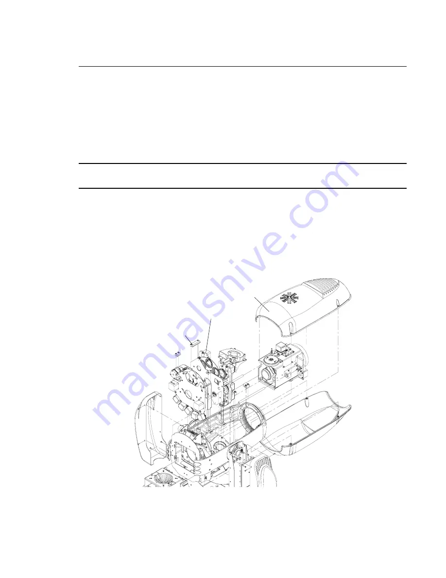
Repair/Replacement Procedure
Step
1. Disconnect luminaire AC input cable from power source.
Step
2. Remove top head cover by loosening four 1/4 turn captive stud connectors.
Note:
The top cover is easily identified as follows - maneuver head so the printing on the label on the
rear of the head assembly is oriented correctly.
Step
3. Disconnect wiring harness from interconnect PCB.
Step
4. Remove interconnect PCB by pushing top of PCB off studs.
Step
5. Loosen four captive screws (two per clamp). (Note: Do NOT remove long phillips head
screw, it serves as a handle.)
Step
6. Pull assembly straight up and out of luminaire.
Step
7. Replace assembly by performing steps 2 through 6 in reverse order.
Figure 2-7: VL3000 Color/Dimmer/Strobe Assembly Replacement
Color/Dimmer/Strobe Assembly
Top Head Cover
Clamp
Summary of Contents for VL3000
Page 1: ......
Page 13: ...FOREWORD 02 9678 0010 G xi ...
Page 14: ...VARI LITE VL3000 VL3000 Q SERVICE MANUAL xii 02 9678 0010 G ...
Page 74: ...VARI LITE VL3000 VL3000 Q SERVICE MANUAL 56 02 9678 0010 G Notes ...
Page 158: ...VARI LITE VL3000 VL3000 Q SERVICE MANUAL 140 02 9678 0010 G Notes ...
Page 164: ...VARI LITE VL3000 VL3000 Q SERVICE MANUAL 146 02 9678 0010 G Notes ...
Page 216: ...VARI LITE VL3000 VL3000 Q SERVICE MANUAL 198 02 9678 0010 G Notes ...
Page 217: ......


