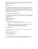
- Disconnect RF cable from Rx In.
- Make a test set up as above for AGC calibration.
-
Select RF frequency and level say -40 dBm and calibrate it for the correct O/P
level.
-
Put ON RF O/P and monitor AGC voltage.
-
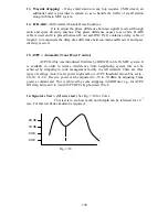
Note down AGC voltage up to -75 dBm in steps of -10 dBm and there after in 5
dBm steps when E
-3
LED lights.
-
Reading will be -86 to -89 dBm.
-
Limit is -86 dBm at Rx IN.
-
This will be a squelch point,
-
Though -35 dBm is an overload point but do not take risk to reach at -35 dBm just
to avoid damage of receiver.
-
Go back to restore the E
-3
LED to monitor hysterics point.
-
Repeat test for protection channel.
4.
Check of alarms: -
Verify the following alarm by simulating the conditions.
a.
Rx select
b.
Tx select
c.
Tx power low
d.
E
-6
AGC voltage
e.
E
-3
Ground
f.
Data unlock
g.
RLO unlock
h.
Data fail
i.
RF fail
j.
Synch. fail
k.
BER LED O.K
l.
Alarm in BITE O.K
m.
AIS
5.
Bay Meter readings: -
-
AGC voltage for both channels.
-
P/S checks -48 and +12.8 V.
-
BER E
-3
and E
-6.
6.
Check of Mux Equipment :-
-
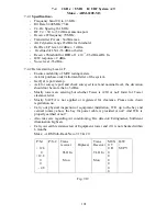
There are four 2 Mb tributaries.
-
Loop IF Out to IF In.
-
Connect DTA set TX and Rx to1
st
Trbs TX and Rx on DDF.
-
Observe loop OK and monitor for 5 minutes for 0 and ±50 PPM.
-
Repeat BER test for other 3 Trbs also.
lease note that after Local A/T is over write Punch points to the installer and
roceed for Through A/T only when all points have been attended by the installer.
P
p
193
Summary of Contents for TW0200
Page 1: ...Chapter 7 ...
Page 2: ...153 ...
Page 3: ...154 ...
Page 4: ...155 ...
Page 5: ......
Page 6: ...157 ...
Page 7: ...158 ...
Page 10: ...161 ...
Page 11: ...162 ...
Page 12: ...163 ...
Page 13: ...164 ...
Page 14: ...165 ...
Page 15: ...166 ...
Page 16: ...167 ...
Page 17: ...168 ...
Page 18: ...169 ...
Page 19: ...170 ...
Page 20: ...171 ...
Page 21: ...172 ...
Page 23: ...174 ...
Page 26: ...177 ...
Page 28: ...179 ...
Page 29: ...180 ...
Page 41: ...192 ...


