


182
. Check of BER with IF Loop: -
oop IF Trans to If Receive and test 140 Mb/ STM-1 on DTA set for 0 PPM and ± 15
PPM. The result should be 0.00 E
-11
5. a) Trans Branching Filter loss: -
The difference between Trans Power at PA out and antenna port will be a Trans
Branching Filter loss.
b) Receive Filter loss: -
Feed RF Frequency at a nominal level to antenna port and measure at Rx in,
Calculate receive filter loss.
Limit: - Tx + Rx combined filter loss should be 6 dB max.
6.
Isolation between Transmitter and Receiver:-
-
TX – Rx
-
Keep Transmitter ON, for Tx – Rx isolation.
-
Tune the transmitter frequency at RRF in point on spectrum analyzer.
-
Limit: Better than 70 dB
-
Rx-Tx
-
Feed Rx RF at antenna port and measure at co-axial cable connected to PA out ,
-
Limit: Better than 70 dB
7. Waveguide pressurization in Kg/ Cm
2
-
Note down Waveguide pressure in Kg/ Cm
2
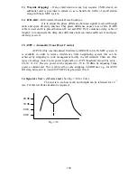
8. Some test of 7 GHz system: -
ALC Test (Automatic level control)
-
Make the test set up as below Fig. 7-14
-
feed -3 dBm to IF in
-
30 dBm at PA out
-
Vary IF level from -1 to -7 dBm
-
Observe level at PA out which should be near about constant , one example,
-
IF PA
-1 +30.000
-3 +30.05
-5 +29.99
-7 +30.05
Fig. 7-14
Low Transpower alarm:-
-
Same set up ALC and go IF level low to see Transpower alarm LED to glow
by 3 dB minimum
-
This alarm on display shows at > 33 dBm and < 25 dBm Transpower
-
Go low by 1 dB step to get this alarm.
4
L
System
analyzer
IF O/P Level
is varied
IF O/P
70 MHz
Power meter
RF out at Eqpt. top
182
Summary of Contents for TW0200
Page 1: ...Chapter 7 ...
Page 2: ...153 ...
Page 3: ...154 ...
Page 4: ...155 ...
Page 5: ......
Page 6: ...157 ...
Page 7: ...158 ...
Page 10: ...161 ...
Page 11: ...162 ...
Page 12: ...163 ...
Page 13: ...164 ...
Page 14: ...165 ...
Page 15: ...166 ...
Page 16: ...167 ...
Page 17: ...168 ...
Page 18: ...169 ...
Page 19: ...170 ...
Page 20: ...171 ...
Page 21: ...172 ...
Page 23: ...174 ...
Page 26: ...177 ...
Page 28: ...179 ...
Page 29: ...180 ...
Page 41: ...192 ...