background image

Published by JH 0671 BG CD Customer Service

Printed in the Netherlands

Subject to modification

EN 3122 785 16510

©

Copyright 2006 Philips Consumer Electronics B.V. Eindhoven, The Netherlands.

All rights reserved. No part of this publication may be reproduced, stored in a 
retrieval system or transmitted, in any form or by any means, electronic, 
mechanical, photocopying, or otherwise without the prior permission of Philips.

Colour Television

Chassis

TES1.0E

LA

G_16510_000.ep

s

2

3

1106

Contents

Page

1.

Technical Specifications, Connections, and Chassis 
Overview

2

2.

Safety Instructions, Warnings, and Notes

5

3.

Directions for Use

7

4.

Mechanical Instructions

8

5.

Service Modes, Error Codes, and Fault Finding 14

6.

Block Diagrams, Test Point Overviews, and 
Waveforms
Power Supply Block Diagram

15

Main Block Diagram

16

Switch Board Block Diagram

17

Main I2C Diagram

18

Tuner I2C Diagram

19

7.

Circuit Diagrams and PWB Layouts

Diagram PWB

Main Board

20-29

30-31

Control Board

32

33

IR & LED Board

34

35

Mains Switch Board

36

37

Side I/O Board

38

39

Switch Board

40

41

8.

Alignments

43

9.

Circuit Descriptions, Abbreviation List, and IC Data 
Sheets

45

Abbreviation List

46

IC Data Sheets

48

10. Spare Parts List

57

11. Revision List

75

Summary of Contents for TES1.0E LA

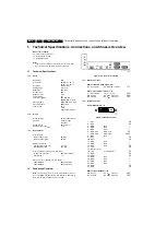
Page 1: ...pecifications Connections and Chassis Overview 2 2 Safety Instructions Warnings and Notes 5 3 Directions for Use 7 4 Mechanical Instructions 8 5 Service Modes Error Codes and Fault Finding 14 6 Block Diagrams Test Point Overviews and Waveforms Power Supply Block Diagram 15 Main Block Diagram 16 Switch Board Block Diagram 17 Main I2C Diagram 18 Tuner I2C Diagram 19 7 Circuit Diagrams and PWB Layout...

Page 2: ...ature range C 5 to 40 Maximum humidity 99 R H Power consumption values are indicative Normal operation W 100 26 130 32 Stand by W 3 Dimensions incl stand W x H x D in mm 26PF1000 62 825 x 486 x 207 32PF1000 62 985 x 546 x 213 1 2 Connection Overview Note The following connector colour abbreviations are used acc to DIN IEC 757 Bk Black Bu Blue Gn Green Gy Grey Rd Red Wh White and Ye Yellow Figure 1...

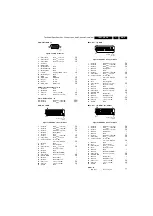
Page 3: ...0 Video in 1 VPP 75 ohm j 21 Shield Gnd H EXT2 AV opt RGB Figure 1 5 SCART connector EXT2 1 Audio R 0 5 VRMS 1 kohm k 2 Audio R 0 5 VRMS 10 kohm j 3 Audio L 0 5 VRMS 1 kohm k 4 Ground Gnd audio H 5 Ground Gnd H 6 Audio L 0 5 VRMS 10 kohm j 7 Video Blue 0 7 VPP 75 ohm j 8 Function Select 0 2 V INT 4 5 12 V EXT 4 3 j 9 Ground Gnd H 10 Res Clock signals 11 Video Green 0 7 VPP 75 ohm j 12 Res Remote c...

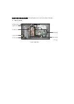
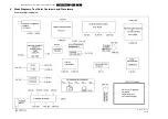
Page 4: ...tions Connections and Chassis Overview EN 4 TES1 0E LA 1 1 3 Chassis Overview Figure 1 7 PWB locations G_16510_012 eps 221106 MAINS SWITCH MAIN BOARD SWITCH BOARD POWER SUPPLY SIDE I O BOARD IR LED BOARD KEYBOARD CONTROL ...

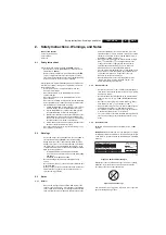
Page 5: ...This will prevent any short circuits and the danger of a circuit becoming unstable 2 3 Notes 2 3 1 General Measure the voltages and waveforms with regard to the chassis tuner ground H or hot ground I depending on the tested area of circuitry The voltages and waveforms shown in the diagrams are indicative Measure them in the Service Default Mode see chapter 5 with a colour bar signal and stereo sou...

Page 6: ...number see Figure 2 1 is composed From this date on the third digit in the serial number example AG2B0335000001 indicates the number of the alternative BOM Bill of Materials used for producing the specific model of TV set It is possible that the same TV model on the market is produced with e g two different types of displays coming from two different O E M s By looking at the third digit of the se...

Page 7: ...Directions for Use EN 7 TES1 0E LA 3 3 Directions for Use You can download this information from the following websites http www philips com support http www p4c philips com ...

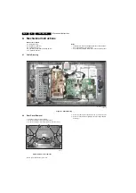
Page 8: ...ons Follow the disassemble instructions in the described order 4 1 Cable Dressing Figure 4 1 Cable Dressing 4 2 Rear Cover Removal 1 Put the set face down on a table 2 Remove fixation screws 1 and the stand 3 Remove fixation screws 2 and remove the rear cover Figure 4 2 Rear cover removal Before you assemble the rear cover 1 Place the strain relief of the mains cord correctly in its slot 2 Place a...

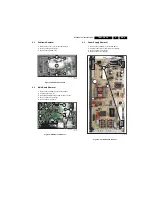
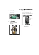
Page 9: ... above 2 Unplug connectors 1 3 Carefully unplug the fragile LVDS connector 2 4 Remove fixation screws 3 5 Remove the main board Figure 4 4 Main board removal 4 5 Power Supply Removal 1 Remove the subframe as described above 2 Unplug connectors 1 from the power supply 3 Remove fixation screws 2 4 Remove the power supply Figure 4 5 Power supply removal G_16510_009 eps 171106 1 1 2 G_16510_011 eps 16...

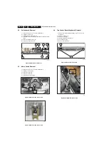
Page 10: ...ove 2 Unplug connectors 1 3 Remove screws 2 4 Remove screws 3 5 Remove the mains switch Figure 4 7 Mains switch removal 1 2 Figure 4 8 Mains switch removal 2 2 4 8 Top Control Board Keyboard Removal 1 Remove the mains switch partially to get access to the keyboard 2 Unplug connector 1 3 Remove screws 2 4 Pull the keyboard out of the set 5 De solder wires 3 6 Remove the keyboard Figure 4 9 Keyboard...

Page 11: ...s described above 2 Unplug connectors 1 3 Remove screws 2 4 Remove the side I O board Figure 4 12 Side I O board removal 4 11 Speaker Removal 1 Remove the rear cover as described above 2 De solder the wires 1 from the speaker contacts 3 Remove screws 2 4 Remove the speaker 5 At installation of a new speaker also glue a piece of foam to the speaker Figure 4 13 Speaker removal G_16510_014 eps 171106...

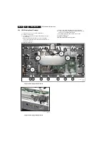
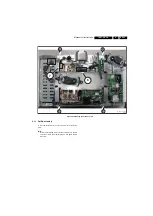
Page 12: ...put them on the frame of the set 4 Remove screws 4 5 Remove the screw that fixates the ground wire 5 6 Lift the frame with the display panel from the front cover and put it on an appropriate surface 7 Carefully unplug the fragile LVDS connector 6 8 Unplug connector 7 9 Remove screws 8 10 Lift the frame from the display panel Figure 4 14 Display panel removal 1 3 Figure 4 15 Display panel removal 2...

Page 13: ...el removal 3 3 4 13 Set Re assembly To re assemble the whole set execute all processes in reverse order Note While re assembling make sure that all cables are placed and connected in their original position See figure Cable dressing G_16510_024 eps 221106 6 7 8 8 8 8 ...

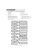
Page 14: ...t Finding and Repair Tips Notes It is assumed that the components are mounted correctly with correct values and no bad solder joints Before any fault finding actions check if the correct options are set The Service Menu contains some useful tests e g ADE pattern in de Scaler Setup Menu that generates patterns Figure 5 1 Fault finding power supply Check 220 V AC Mains Check C 324 Voltage Check 5VST...

Page 15: ...Block Diagrams Test Point Overviews and Waveforms 15 TES1 0E LA 6 6 Block Diagrams Test Point Overviews and Waveforms Power Supply Block Diagram G_16510_056 eps 211106 ...

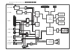
Page 16: ...24 bit DIGITAL RGB LVDS BUS LCD IF1 IF2 MAIN TUNER CVBS MONO SIF PIP TUNER CVBS ITU656 BUS PIP PIC MAIN RGB DIGITAL YUV BUS MAIN TUNER PIP TUNER SCARTS S VIDEO AUDIO S VIDEO AV IN or OUT PC INPUT PC DVI AUDIO DVI INPUT FRONT AV HEADPHONE MULTIBUTTON LED INFRA IF DEMODULATOR IF DEMODULATOR VIDEO SWITCH RGB SWITCH AUDIO SWITCH HP AMPLIFIER SOUND PIP VIDEO VIDEO SCALER AUDIO POWER LVDS TRANSMITTER PR...

Page 17: ...iagrams Test Point Overviews and Waveforms 17 TES1 0E LA 6 Switch Board I2C Block Diagram 1 2 3 4 5 6 A B C D 6 5 4 3 2 1 D C B A SDA1 SCL1 2 2 4 4 TEA6415C TEA6415C R252 R253 R210 R211 G_16510_054 eps 211106 ...

Page 18: ...s Main I2C Diagram R665 R666 EEPROM MCU ADE3300 PVP9390 STV2310 STV8216 R302 R R303 R R122 R R123 R R110 R R111 R R846 R R847 R 3 3V 5V SDA1_5V SCL1_5V SCL1_3 3V SDA1_3 3V SDA2_3 3V SCL2_3 3V SCL3_3 3V SDA3_3 3V TO SWITCH BOARD TO TUNER BOARD G_16510_053 eps 211106 ...

Page 19: ...s and Waveforms 19 TES1 0E LA 6 Tuner I2C Diagram 1 2 3 4 5 6 A B C D 6 5 4 3 2 1 D C B A 10 11 10 11 4 5 4 5 TEDE9 736A CTF5513A TDA9886 TDA9886 SDA 1 SCL 1 R414 R R415 R R417 R R418 R R444 R R445 R R438 R R439 R G_16510_055 eps 211106 ...

Page 20: ...09 FERRITE 1 8V 6V 5VS 9V 1 2 3 IN OUT GND U902 LF33C 1 2 3 IN OUT GND U903 LF18C 1 2 3 4 5 6 S804 DVD IDTV WIRELESS INTERFACE R837 220R C939 100nF C948 470uF V_TFT 1 2 3 4 5 6 S103 POWER 5V 9V PORT_A PORT_B PORT_C PORT_D MUTE_IN 16V 16V MUTE_REF BL_ON OFF TFT_ON OFF BL_DIMM R248 4 7K 3 3VS R247 4 7K 5VS R246 470R R252 2 2K R249 1K C376 56pF C266 100nF C290 100uF Q201 BC848 PWM_DIMM PWM_DIMM A_DIM...

Page 21: ...5 G6 G7 B0 B1 B2 B3 B4 B5 B6 B7 PWRD L911 BEAD L912 BEAD C900 100nF C906 100nF C924 10uF C933 10uF R900 0R R904 120R R903 120R 3 3V 3 3V 3 3V RIN0 RIN1 RIN2 RIN3 RCLK RCLK RIN0 RIN1 RIN2 RIN3 V_TFT RIN0 RIN1 RIN2 RIN3 RCLK RCLK RIN0 RIN1 RIN2 RIN3 1 2 3 4 5 6 7 8 9 10 11 12 13 14 15 16 17 18 19 20 21 22 23 24 25 26 27 28 29 30 S903 CON2X15 L914 BEAD LG L913 BEAD LG hariç R901 0R R906 R R902 0R BL_...

Page 22: ...Q2 5 DQ3 7 DQ4 8 DQ5 10 DQ6 11 DQ7 13 DQ8 42 DQ9 44 DQ10 45 DQ11 47 DQ12 48 DQ13 50 DQ14 51 DQ15 53 L_DQM 15 U_DQM 39 RFU NC 40 VSSQ 46 VSSQ 52 VDD 1 VDD 14 VDD 27 VSS 28 VSS 41 VSS 54 VDDQ 3 VDDQ 9 VDDQ 43 VDDQ 49 U701 48LC8M16A2 C705 100nF C702 10uF 3 3VRAM ADDR0 ADDR1 ADDR2 ADDR3 ADDR4 ADDR5 ADDR6 ADDR7 ADDR8 ADDR9 ADDR10 ADDR11 ADDR15 ADDR16 RD_NOTWR NOT_CAS NOT_RAS CKOUT NOT_CS_SDRAM ADDR12 S...

Page 23: ...F R165 22K L120 10uH 5VTUNER R170 100R R169 1K C243 100nF GND SDA1_5 SCL1_5 L113 10uH L125 BEAD SIF C184 100nF D102 LL4148 D100 LL4148 C119 1uF MONO_AUDIO R168 330R C226 10pF C244 10uF R174 10R R176 47R R175 1K R171 1K C240 100nF R173 100R CVBS CVBS_TUNER1 R197 75R R151 NS R183 NS L124 BEAD 5VTUNER L128 BEAD C362 390pF C233 390pF 5VTUNER C355 10nF Q104 BC848B Q106 BC848B Q105 BC848B Q107 BC848B C1...

Page 24: ...C849 10uF C845 390pF L803 BEAD C847 100nF R846 100R R847 100R SDA1_3 SCL1_3 HSYNC_PIP VSYNC_PIP Y800 20 25MHZ C826 27pF C825 27pF C841 10nF C843 10uF C840 390pF L808 BEAD 1 8V C842 100nF STV_FB STV_B STV_G R819 75R STV_R R820 10K R821 10K R822 10K R823 NS R829 NS R830 NS R831 NS R839 NS SC1_R SC1_G SC1_B SC1_FB C817 10nF C824 10uF C816 390pF L807 BEAD 1 8V C818 100nF R802 100R 1 8V R838 75R C819 7...

Page 25: ...VIDEO0 202 P_VIDEO1 203 P_VIDEO2 204 P_VIDEO3 205 P_VIDEO4 206 VDD33_IO 207 P_VIDEO5 208 VSS_IO 105 U601 STV3550 P6 P7 P8 P9 P10 P11 SD0 SD1 SD2 SD3 SD4 SD5 SD6 SD7 SD8 SD9 SD10 SD11 SD12 SD13 SD14 SD15 ADR13 NOTBE1 ADR4 ADR5 ADR6 ADR7 ADR8 ADR9 ADR11 ADR12 CKSD CKOUT ADR0 ADR1 ADR2 ADR3 ADR10 ADR16 ADR15 NOTCSSRD NOTRAS NOTCAS RDNOTWR NOTBE0 NCSFLS ADR17 ADR18 ADR19 ADR14 FLASHD15 FLASHD7 FLASHD1...

Page 26: ...5 6 7 8 RN30 33R 1 2 3 4 5 6 7 8 RN31 33R 1 2 3 4 5 6 7 8 RN33 33R YC Y0 Y1 Y 7 Y 8 Y 9 Y10 Y11 C310 100nF R300 100K 5V ADE_RESET C311 100nF R301 220K 3 3DV SDA3_3 SCL3_3 1 8DV 3 3DV R307 22R OVS OCLK OHS ODE R0 R1 R2 R3 R4 R5 R6 R7 G0 G1 G2 G3 G4 G5 G6 G7 B0 B1 B2 B3 B4 B5 B6 B7 3 3AV 1 8AV CSYNC V_SYNC H_SYNC R310 15K C384 470nF C368 100pF BLUE PB C363 100nF R311 15K C385 470nF C369 100pF GREEN ...

Page 27: ...0uH R215 0R R214 22R 5V R204 220R R205 220R C245 330pF C246 330pF L216 100uH C284 33nF L217 100uH L219 100uH L218 100uH C285 33nF C286 33nF C287 33nF C228 10uF 1 8V R216 0R 3 3V C273 18pF C275 18pF L215 100uH L214 100uH R208 0R R207 0R 3 3V L208 10uH L209 10uH L204 10uH L210 10uH L203 10uH NRESET C235 10uF C237 10uF L205 10uH C258 100nF R206 100R INA 1 INA 2 INB 3 INB 4 GND 5 OUTA 6 OUTB 7 VDD 8 U...

Page 28: ...12 68R CLOCKDATA PLL_LOCK C137 390pF C125 100nF C107 10uF 3 3VOUT C138 390pF C126 100nF C108 10uF 1 8VOUT 1 8VA C134 390pF C122 100nF CLKXTP CLKXTM C153 330pF R113 0R STV_FB C132 390pF C117 100nF C133 390pF C118 100nF C150 330pF C149 22nF R106 220R R109 270R C157 270pF C160 180pF C144 10pF L103 3 3uH STV_R C146 22nF R104 220R R107 270R C155 270pF C158 180pF C142 10pF L101 3 3uH STV_G C130 390pF C1...

Page 29: ...05 10K R406 10K H_SYNC V_SYNC L404 BEAD 5V C408 100nF C416 100pF ANALOG_RED ANALOG_GREEN ANALOG_BLUE VGA_HS VGA_VS R407 10K Q400 BC848 C421 470pF TP225 TP227 TP228 TP229 TP230 TP231 TP232 TP233 TP234 TP235 TP236 TP237 Q606 BC848B Q607 BC848B R656 47K R655 47K R652 10K R650 100R 3 3VS 5VS Q604 BC848B Q605 BC848B R654 47K R653 47K R651 10K R649 100R 3 3VS 5VS SDA1_3 SDA1_5 SCL1_5 SCL1_3 Q102 BC848B ...

Page 30: ...30 TES1 0E LA 7 Circuit Diagrams and PWB Layouts Layout Main Board Top Side G_16510_026 eps 201106 05TA059A ...

Page 31: ...Circuit Diagrams and PWB Layouts 31 TES1 0E LA 7 Layout Main Board Bottom Side G_16510_027 eps 201106 05TA059A ...

Page 32: ...A B C D 4 3 2 1 D C B A 1 2 S001 To main pcb C001 100nF R002 5 6K 1 6W R003 2 7K 1 6W R004 1 5K 1 6W R005 820R 1 6W R007 220R 1 6W R006 470R 1 6W SW02 MENU SW03 SOURCE SW04 V SW05 V SW06 P SW07 P MULTI BUTTON SEMA GND 1 2 S002 To infra pcb C002 100nF G_16510_038 eps 201106 05TA052A ...

Page 33: ...Circuit Diagrams and PWB Layouts 33 TES1 0E LA 7 Layout Keyboard Control Board Top Side Layout Keyboard BoardControl Board Bottom Side G_16510_039 eps 201106 05TA052A G_16510_040 eps 201106 05TA052A ...

Page 34: ...NFRA RED R001 33R 1 4W C001 100uF GND R003 470R R004 15K 1 6W SW01 STBY 1 2 S002 To mbutton pcb C002 100nF IR 3 VCC 2 GND 1 IR01 IR LED1 LED G_16510_041 eps 221106 05TA053B Layout IR LED Board Top Side Layout IR LED Board Bottom Side G_16510_042 eps 201106 05TA053B G_16510_043 eps 201106 05TA053B ...

Page 35: ...d PWB Layouts 35 TES1 0E LA 7 Mains Switch Board 1 A B C D 1 D C B A 4 2 3 1 POW1 POWER 1 2 S100 POWER 1 2 S101 POWER POWER G_16510_044 eps 221106 05TA081 Layout Mains Switch Board Top Side G_16510_045 eps 211106 05TA081 ...

Page 36: ...F C113 1nF L111 BEAD R103 15K AV_R C110 1nF C114 1nF C116 1nF AGND AGND AGND AGND AGND AGND AGND AGND 1 2 3 S100 HEADFGND GND L R AGND L100 22uH L101 22uH C100 220nF GND C101 220nF GND C102 100nF GND C103 100nF GND R100 4 7R C104 10nF GND R101 4 7R C105 10nF GND FD1 FD2 FD3 1 2 3 S101 CON3 1 2 3 4 5 S103 CON5 5 4 3 2 1 6 S102 CHINC3 G_16510_046 eps 211106 05TA051D ...

Page 37: ...it Diagrams and PWB Layouts 37 TES1 0E LA 7 Layout Side I O Board Top Side Layout Side I O Board Top Side G_16510_047 eps 211106 05TA051D G_16510_048 eps 211106 05TA051D Personal Notes E_06532_012 eps 131004 ...

Page 38: ... 22 23 24 25 26 27 28 29 30 31 32 33 34 35 36 37 38 39 40 S201 1 2 3 4 5 6 7 8 9 10 11 12 13 14 15 16 17 18 19 20 21 22 23 24 25 26 27 28 29 30 31 32 33 34 35 36 37 38 39 40 S202 VCC 34 TV IN 47 V1 IN 1 V2 IN 8 V3 IN 15 V4 IN 23 Y1 IN 3 Y2 IN 10 Y3 IN 17 C1 IN 5 C2 IN 12 C3 IN 19 LTV 46 LV1 2 LV2 9 LV3 16 LV4 22 RV1 4 RTV 48 RV2 11 RV3 18 RV4 24 S2 1 6 S2 2 13 S2 3 20 S 1 7 S 2 14 S 3 21 VOUT1 40 ...

Page 39: ...0 1 2K R216 NS R241 75R R231 1 2K R217 NS R242 75R R243 75R R234 1 2K R218 NS R219 NS R236 1 2K R245 75R R247 75R R221 NS R238 1 2K R249 75R R239 1 2K R223 NS R251 75R R255 0R R254 0R R253 220R R252 220R R212 1K R237 1 2K R227 1 2K C239 NS C235 100nF FRONT_V SC1_CVBS SC2_CVBS SC3_CVBS LUMA CHROMA SC2_CHROMA SC2_ALI SC2_ARI SC3_ARI SC3_ALI S_VIDEO_L S_VIDEO_R PC DVI_L PC DVI_R 9V PIP_VIDEO PIP_CHRO...

Page 40: ...R R195 100R R194 100R TP98 TP97 TP96 TP94 TP41 TP42 TP36 TP37 TP68 TP66 TP65 TP63 TP62 TP67 TP88 TP89 TP43 TP44 TP61 TP95 TP64 TP100 1 2 3 4 5 S107 PC SERVICE 1 2 3 4 5 S113 DVI SERVICE WP_PC VGA_SCL VGA_SDA 5V 5V WP_DVI DVI_DDSDA DVI_DDSCL WP_PC R276 75R R291 75R R290 75R C232 100nF C229 100nF C233 100nF C234 100nF C224 100nF R269 NS R248 NS R270 0R R271 0R R272 0R R151 100R R150 100R TXD RXD 1 4...

Page 41: ...5K S_VIDEO_R FRONT AV SCART1 SCART2 SCART3 C136 1nF C138 1nF C139 1nF C141 1nF C140 1nF R137 15K R138 15K C143 1nF C142 1nF C145 1nF R140 15K C144 1nF R139 15K C147 1nF R142 15K C146 1nF R141 15K C149 1nF C148 1nF C151 1nF C150 1nF L116 BEAD R129 NS 1 2 3 4 5 S104 CON5 R131 75R R134 75R 9V 5V C137 470uF L123 10uH C155 100nF C152 10uF L124 10uH C156 100nF C157 10uF C158 10uF C161 10uF C162 10uF C15...

Page 42: ...9V Q205 BC848 R268 1K R275 150K R258 100K C243 1uF R283 470R R282 470R DVD_L DVD_L_SW DVD_L_LINE 9V Q204 BC848 R267 1K R274 150K R257 100K C242 1uF R281 470R R277 470R DVD_R DVD_R_SW DVD_R_LINE TP148 TP156 TP157 C245 47uF 1 2 3 4 5 S204 DVD OUT COAX DVD_R_LINE DVD_L_LINE C252 NS C253 NS R273 0R C254 NS TP158 TP159 TP153 TP154 TP155 TP151 TP152 TP147 TP149 TP150 TP145 TP144 TP143 TP141 TP146 TP142 ...

Page 43: ...Circuit Diagrams and PWB Layouts 43 TES1 0E LA 7 Layout Switch Board Top Side Layout Switch Board Top Side G_16510_050 eps 211106 05TA079C G_16510_051 eps 211106 05TA079C ...

Page 44: ...44 TES1 0E LA 7 Circuit Diagrams and PWB Layouts Personal Notes E_06532_013 eps 131004 ...

Page 45: ...nutes Measure the voltages and waveforms in relation to chassis ground with the exception of the voltages on the primary side of the power supply Never use the cooling fins plates as ground Test probe Ri 10 Mohm Ci 2 5 pF Use an isolated trimmer screwdriver to perform the alignments 8 3 Hardware Alignments There are no hardware alignments present in the sets 8 4 Software Alignments 8 4 1 Service M...

Page 46: ...t 13 Steps 6 to 6 PreScl FM 31 Steps 6 to 24 PreScl NICAM 31 Steps 6 to 24 Nic Switch Thrs 4 Steps 0 to 3 PreScl Mono 13 Steps 6 to 6 Smart Volume ON OFF Smart Volume Level 2 4 8 16 Sound System System BG ON OFF System DK ON OFF System I ON OFF System M ON OFF Default System BG DK I M Scaler Setup SRGB Block ON OFF ADE Pattern ON OFF test pattern created by the ADE3300 Scaler chip ADE Pattern Auto...

Page 47: ... 2 Basic Hardware Descriptions No information available 9 3 Block Diagrams 9 3 1 Main Block Diagram Figure 9 1 Main block diagram PLL TUNER PLL TUNER SCART CVBS SCART RGB FB SCART AUDIO IN OUT SCART1 AUDIO IN S VIDEO AUDIO S VIDEO Y C BACK AV VIDEO IN or OUT BACK AV AUDIO IN or OUT PC VGA INPUT PC and DVI AUDIO INPUT DVI D Single Link INPUT FRONT AV VIDEO INPUT FRONT AV AUDIO INPUT HEADPHONE L HEA...

Page 48: ...CVI Component Video Input D K Monochrome TV system Sound carrier 6 5 MHz EEPROM Electrically Erasable and Programmable Read Only Memory EW East West related to horizontal deflection of the set EXT External source entering the set via SCART or Cinch Can either be Ext 1 or Ext 3 FM Frequency Modulation I Monochrome TV system Sound carrier 6 0 MHz I2C Integrated IC bus I F Intermediate Frequency LED ...

Page 49: ...ms The customer can give directly the desired frequency QSS Quasi Split Sound Sound IF application used for stereo sound RAM Random Access Memory RC Remote Control handset RC5 Remote Control code standard RGB Red Green and Blue video signals ROM Read Only Memory S C Short Circuit Scart Peri television interconnection 42 pin or 21 pin euro connector SCL Serial Clock SECAM Colour system used e g in ...

Page 50: ...3 FL AS H_ D10 FL AS H_ D2 FL AS H_ D9 FL AS H_ D1 FL AS H_ D8 FL AS H_ D0 VDD33_I O VS S_ IO POR TC0 PORTA0 PORTD4 PORTA1 POR TD7 PORTA4 VDD33_IO PORTA5 POR TA6 PORTA7 VDD33_IO VSS_IO POR TD5 PORTC7 PORTC6 PORTC5 POR TC4 PORTD0 PORTD1 POR TD2 PORTD3 VDD33_IO PORTD6 POR TA2 PORTA3 VSS_IO PORTB5 PORTB4 PORTB3 PORTB2 PORTB1 PORTB0 VDD33_IO VCC33_ADC GND_ADC SHIELD_ADCDAC V100 H100 CLK_DFL DCLK VSS _...

Page 51: ...00 U300 Figure 9 4 Internal block diagram and pin configuration of the LCD Monitor Controller Block Diagram Pin Configuration G_16510_062 eps 221106 YUV PORT Analog PORT DVI PORT SCALER SCLK F SYNTH P GEN TCON OUTPUT FORMAT FM F SYNTH LLKPLL DMEAS SMEAS INCLK SCLK DOTCLK COLOR MANAGEMENT OSD GAMMA LUT DATA CTRL ...

Page 52: ... Separator Synchronization and IC Monitoring Clock VSYNC Field G B Cb STV2310 YCRC B 5 YCRC B 4 VSS_IO VDD3 3_IO YCRC B 3 YCRC B 2 YCRC B 1 YCRC B 0 VDD1 8_OUT VSS_OUT CL K_ DATA PLL LOCK VDD1 8_CORE VSS YCRC B 7 YCRC B 6 64 63 62 61 60 59 58 57 56 55 54 53 52 51 50 49 48 47 46 45 44 43 42 41 40 39 38 37 36 35 34 33 17 18 19 20 21 22 23 24 29 30 31 32 25 26 27 28 1 2 3 4 5 6 7 8 9 10 11 12 13 14 1...

Page 53: ...ol Voltage TU 2 Tuning voltage monitor output AS 3 I 2 C Bus Address Select SCL 4 I 2 C Bus Serial Clock SDA 5 I 2 C Bus Serial Data n c 6 Not Connected Vs 7 Supply Voltage 5V ADC 8 ADC Input 5 VST 9 Fixed tuning Supply Voltage 33V I F out 2 d n c 10 Symmetrical I F output 2 Do not connect for asymmetrical I F out 1 11 Asymmetrical I F Output Symmetrical I F output 1 GND M1 M2 M3 M4 Mounting Tags ...

Page 54: ...06 PLL 1 2 3 5 6 7 9 Vt 10 11 IF2 IF1 AGC Tu AS SCL SDA 5V 5V 5V VL VH UHF UHF VL VH 5V 4 For CTF 5510A 5511 5512 5513 5515 5516 and 5517 Pin Symbol Description 1 AGC Automatic gain control 2 TU For production process usage 3 AS Tuner Address Select 4 SCL I2C serial clock 5 SDA I2C serial data 6 UB 5V supply voltage 7 5V Internal connection to pin 6 8 N C 9 Vt Tuning voltage 32V 10 IF2 IF output b...

Page 55: ...C 8bit Triple DAC 3x7bit IN1 IN3 FSW OUT1 OUT2 OUT3 SEL Fast RGB YUV Switch IN2 VDD33DAC VSS33DAC VDD18 VSS18 CVBS1 CVBS2 CVBS3 VSS33ADC VDD18ADC XIN XQ I2C1 SCL SDA HSP VSP XTAL 20 25 MHz INTR CVBS4 Y U V CLKOUT GP0 2 I2C2 VDD33PAD VSS33PAD VSS18ADC VDD33ADC RESET PVP 9390A Block Diagram Pin Configuration G_16510_057 eps 221106 34 35 36 37 38 39 40 41 42 43 44 22 21 20 19 18 17 16 15 14 13 12 1 2...

Page 56: ...rms SC K SD O WS I2C Interface Gain Audio Matrix Output Analog Low Noise Audio Mute Low Noise Audio Mute 2Vrms 2Vrms AO1L AO1R AO2L AO2R IRQ ST BU S 0 BUS 1 HPD 0 5V rms 2V rms 2Vrms 2Vrms Single Crystal Clock Generation Au dio Matrixing Audio Processing Demodulation XT I XT O Po wer Supply Management DC Regulators Standby mode I2C Bus Expander Input SCART s So und IF Ou tput S car ts Headphone Su...

Page 57: ...iagram and pin configuration of the audio amplifier 5V 18K 15K IN L 1μF 15K 1μF MUTE ST BY GND IN R 1μF 4 7Ω 4 7Ω 100nF 100nF OUT L OUT R 1000μF 1000μF VS 2 4 6 7 5 8 1 3 D94AU069A RL L RL R VS VS μP Block Diagram Pin Configuration G_16510_065 eps 221106 1 2 3 4 5 6 7 8 IN 1 GND IN 2 VS MUTE ST BY OUTPUT 2 VS OUTPUT 1 Tab connected to pin 5 ...

Page 58: ...5 to 6 5 MHz NARROW BAND FM PLL DETECTOR I2C BUS TRANSCEIVER VIF PLL SINGLE REFERENCE QSS MIXER INTERCARRIER MIXER AND AM DEMODULATOR SIF AGC SUPPLY 1 2 14 16 19 15 21 17 8 6 5 4 12 7 11 10 18 20 23 24 OUTPUT PORTS MAD AUDIO PROCESSING AND SWITCHES 9 TUNER AGC CAGC neg 3 22 crystal and MAD select TDA9885 n c 13 L L P M F D A M O I S D N G D A D S L C S 2 P O 1 P O CVBS TOP VIF2 SIF1 SIF2 DEEM AFD ...

Page 59: ...R129 030010600061 RESISTOR C F 0R 1 10W 5 0603 R133 030010600061 RESISTOR C F 0R 1 10W 5 0603 R134 030010600061 RESISTOR C F 0R 1 10W 5 0603 R135 030010600061 RESISTOR C F 0R 1 10W 5 0603 R136 030010600061 RESISTOR C F 0R 1 10W 5 0603 R138 030010600061 RESISTOR C F 0R 1 10W 5 0603 R653 030010600061 RESISTOR C F 0R 1 10W 5 0603 R655 030010600061 RESISTOR C F 0R 1 10W 5 0603 R200 030010600061 RESIST...

Page 60: ...10W5 0603 RN38 030010612001 RES ARRAY C F 120R 1 10W5 0603 RN39 TELRA NO TELRA DESCRIPTION POS 030010612001 RES ARRAY C F 120R 1 10W5 0603 RN40 030010612161 RESISTOR C F 120R 1 10W5 0603 R628 030010612161 RESISTOR C F 120R 1 10W5 0603 R629 030010612161 RESISTOR C F 120R 1 10W5 0603 R630 030010612161 RESISTOR C F 120R 1 10W5 0603 R631 030010612161 RESISTOR C F 120R 1 10W5 0603 R632 030010612161 RES...

Page 61: ...3 R102 030011610261 RESISTOR C F 75R 1 10W1 0603 R103 030011610261 RESISTOR C F 75R 1 10W1 0603 R130 TELRA NO TELRA DESCRIPTION POS 030011610261 RESISTOR C F 75R 1 10W1 0603 R213 030011610261 RESISTOR C F 75R 1 10W1 0603 R402 030011610261 RESISTOR C F 75R 1 10W1 0603 R403 030011610261 RESISTOR C F 75R 1 10W1 0603 R404 030011610261 RESISTOR C F 75R 1 10W1 0603 R819 030011610261 RESISTOR C F 75R 1 1...

Page 62: ...805H151R 00 SMD L126 TELRA NO TELRA DESCRIPTION POS 036070204111 FERRIT BEAD LI0805H151R 00 SMD L107 036070204111 FERRIT BEAD LI0805H151R 00 SMD L110 036070204111 FERRIT BEAD LI0805H151R 00 SMD L111 036070204201 FERRIT ARRAY MZA3216 L700 036070204201 FERRIT ARRAY MZA3216 L702 036070204201 FERRIT ARRAY MZA3216 L703 036070204201 FERRIT ARRAY MZA3216 L704 036070204201 FERRIT ARRAY MZA3216 L705 036070...

Page 63: ...R 0603 C166 040067141061 CAP CER 100NF 50V 10 X7R 0603 C165 TELRA NO TELRA DESCRIPTION POS 040067141061 CAP CER 100NF 50V 10 X7R 0603 C103 040067141061 CAP CER 100NF 50V 10 X7R 0603 C105 040067141061 CAP CER 100NF 50V 10 X7R 0603 C106 040067141061 CAP CER 100NF 50V 10 X7R 0603 C244 040067141061 CAP CER 100NF 50V 10 X7R 0603 C109 040067141061 CAP CER 100NF 50V 10 X7R 0603 C110 040067141061 CAP CER ...

Page 64: ...0NF 50V 10 X7R 0603 C919 040067141061 CAP CER 100NF 50V 10 X7R 0603 C920 040067141061 CAP CER 100NF 50V 10 X7R 0603 C921 TELRA NO TELRA DESCRIPTION POS 040067141061 CAP CER 100NF 50V 10 X7R 0603 C922 040067141061 CAP CER 100NF 50V 10 X7R 0603 C923 040067141061 CAP CER 100NF 50V 10 X7R 0603 C925 040067141061 CAP CER 100NF 50V 10 X7R 0603 C926 040067141061 CAP CER 100NF 50V 10 X7R 0603 C297 04006714...

Page 65: ...CT 470MF 16V 20 C417 042140164771 CAP ELECT 470MF 16V 20 C418 042414251071 CAP ELECT 100MF 25V 20 C277 042414251071 CAP ELECT 100MF 25V 20 C903 042414251071 CAP ELECT 100MF 25V 20 C904 042414254761 CAP ELECT 47MF 25V 20 C176 042416501051 CAP ELECT 1MF 50V 20 C174 TELRA NO TELRA DESCRIPTION POS 042416501051 CAP ELECT 1MF 50V 20 C175 042416501051 CAP ELECT 1MF 50V 20 C230 042416501051 CAP ELECT 1MF ...

Page 66: ...PTION POS 048000000491 DIODE BAS70 04 SWITCHING SOT23 D401 048000000491 DIODE BAS70 04 SWITCHING SOT23 D402 048000000491 DIODE BAS70 04 SWITCHING SOT23 D300 048000000491 DIODE BAS70 04 SWITCHING SOT23 D301 048000000491 DIODE BAS70 04 SWITCHING SOT23 D302 048000000491 DIODE BAS70 04 SWITCHING SOT23 D303 048000000491 DIODE BAS70 04 SWITCHING SOT23 D304 048000000491 DIODE BAS70 04 SWITCHING SOT23 D30...

Page 67: ... OF26 32CFUL PH SC ONOF 966026000020 STRAPHOR 26 COLORFUL TELRA NO TELRA DESCRIPTION POS TELRA NO TELRA DESCRIPTION POS 002013202590 CABLE 2P FLAT 10CM 002013202680 CABLE POW FLTR 94T 2TRM240CMSF 002013202920 CABLE POW 2PX2SKT 10MM 70CM SF S101 002013502131 CABLE 6P 2SKT 10CM MINI S103 002022000981 CABLE 2P 2SKT 80CM MINI S002 002025010781 CABLE 10PX2SKT 16CM 2MM 32 AUO S302 002025010781 CABLE 10P...

Page 68: ...03 R185 030010610161 RESISTOR C F 100R 1 10W5 0603 R186 030010610161 RESISTOR C F 100R 1 10W5 0603 R802 TELRA NO TELRA DESCRIPTION POS 030010610161 RESISTOR C F 100R 1 10W5 0603 R846 030010610161 RESISTOR C F 100R 1 10W5 0603 R847 030010610181 RESISTOR C F 100R 1 8W 5 0805 R245 030010610261 RESISTOR C F 1K 1 10W5 0603 R174 030010610261 RESISTOR C F 1K 1 10W5 0603 R175 030010610261 RESISTOR C F 1K ...

Page 69: ...3 R308 030010647161 RESISTOR C F 470R 1 10W5 0603 R246 030010647261 RESISTOR C F 4 7K 1 10W5 0603 R600 TELRA NO TELRA DESCRIPTION POS 030010647261 RESISTOR C F 4 7K 1 10W5 0603 R602 030010647261 RESISTOR C F 4 7K 1 10W5 0603 R603 030010647261 RESISTOR C F 4 7K 1 10W5 0603 R605 030010647261 RESISTOR C F 4 7K 1 10W5 0603 R606 030010647261 RESISTOR C F 4 7K 1 10W5 0603 R607 030010647261 RESISTOR C F ...

Page 70: ...68321 RES ARRAY C F 68R 1 10W5 0603 RN78 030140668321 RES ARRAY C F 68R 1 10W5 0603 RN79 030140668321 RES ARRAY C F 68R 1 10W5 0603 RN74 030140668321 RES ARRAY C F 68R 1 10W5 0603 RN75 030140668321 RES ARRAY C F 68R 1 10W5 0603 RN76 TELRA NO TELRA DESCRIPTION POS 030140668321 RES ARRAY C F 68R 1 10W5 0603 RN77 030140668321 RES ARRAY C F 68R 1 10W5 0603 RN81 030140668321 RES ARRAY C F 68R 1 10W5 06...

Page 71: ... NO TELRA DESCRIPTION POS 040044081861 CAP CER 470NF 16V 10 X7R 0603 C218 040044081861 CAP CER 470NF 16V 10 X7R 0603 C219 040044081861 CAP CER 470NF 16V 10 X7R 0603 C217 040044081861 CAP CER 470NF 16V 10 X7R 0603 C223 040044081861 CAP CER 470NF 16V 10 X7R 0603 C216 040044081861 CAP CER 470NF 16V 10 X7R 0603 C221 040044081861 CAP CER 470NF 16V 10 X7R 0603 C222 040044081861 CAP CER 470NF 16V 10 X7R ...

Page 72: ...41061 CAP CER 100NF 50V 10 X7R 0603 C354 040067141061 CAP CER 100NF 50V 10 X7R 0603 C356 TELRA NO TELRA DESCRIPTION POS 040067141061 CAP CER 100NF 50V 10 X7R 0603 C357 040067141061 CAP CER 100NF 50V 10 X7R 0603 C358 040067141061 CAP CER 100NF 50V 10 X7R 0603 C359 040067141061 CAP CER 100NF 50V 10 X7R 0603 C360 040067141061 CAP CER 100NF 50V 10 X7R 0603 C361 040067141061 CAP CER 100NF 50V 10 X7R 06...

Page 73: ...061 CAP CER 100PF 50V 5 COG 0603 C370 040732041061 CAP CER 100PF 50V 5 COG 0603 C416 040732042061 CAP CER 120PF 50V 5 COG 0603 C140 040742022261 CAP CER 22NF 50V 5 X7R 0603 C145 TELRA NO TELRA DESCRIPTION POS 040742022261 CAP CER 22NF 50V 5 X7R 0603 C146 040742022261 CAP CER 22NF 50V 5 X7R 0603 C147 040742022261 CAP CER 22NF 50V 5 X7R 0603 C148 040742022261 CAP CER 22NF 50V 5 X7R 0603 C149 0407420...

Page 74: ...ELECT 10MF 50V 20 C934 042446501061 CAP ELECT 10MF 50V 20 C936 TELRA NO TELRA DESCRIPTION POS 042446501061 CAP ELECT 10MF 50V 20 C937 042446501061 CAP ELECT 10MF 50V 20 C938 042446501061 CAP ELECT 10MF 50V 20 C238 042446501061 CAP ELECT 10MF 50V 20 C244 042446501061 CAP ELECT 10MF 50V 20 C302 042446501061 CAP ELECT 10MF 50V 20 C432 042446501061 CAP ELECT 10MF 50V 20 C367 042446501061 CAP ELECT 10M...

Page 75: ...220480021 CONN 30P SMD MX53505 S903 081000000141 SWITCH POWERALPS SDKVA30100SFT POW1 081101111601 SWITCH TACT HRZ MTLCONT 6 6 SW01 TELRA NO TELRA DESCRIPTION POS 081101111601 SWITCH TACT HRZ MTLCONT 6 6 SW02 081101111601 SWITCH TACT HRZ MTLCONT 6 6 SW03 081101111601 SWITCH TACT HRZ MTLCONT 6 6 SW04 081101111601 SWITCH TACT HRZ MTLCONT 6 6 SW05 081101111601 SWITCH TACT HRZ MTLCONT 6 6 SW06 08110111...

Page 76: ...Revision List EN 76 TES1 0E LA 11 11 Revision List 11 1 Manual xxxx xxx xxxxx 0 First release ...

Reviews: