Circuit Descriptions, Abbreviation List, and IC Data Sheets
EN 23
TC5.1L CB
9.
9.2.3
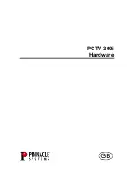
Demultiplexer (IC 901)
The HCF4052B is a monolithic integrated circuit, fabricated in
Metal Oxide Semiconductor technology, available in DIP and
SOP packages.
The HCF4052B analog multiplexer/demultiplexer is a digitally
controlled analog switch, having low ON impedance, and very
low OFF leakage current. This multiplexer circuit dissipates
extremely low quiescent power over the full supply voltage
range, independent of the logic states of the control signals.
When a logic “1” is present at the inhibit input, all channels are
off. This device is a differential 4-channel multiplexer, having 2
binary control inputs, A and B, and an inhibit input. The two
binary input signals select 1 of 4 pairs of channels to be turned
on and connect the analog inputs to the outputs.
Figure 9-9 Demultiplexer
Table 9-3 Demultiplexer
9.2.4
Sound Processor (IC1001)
Table 9-4 Sound Processor
9.2.5
Dual Bridge Amplifier (IC 602)
The TDA7266SA is a dual bridge amplifier, specially designed
for LCD monitor, PC motherboard, TV, and portable radio
applications.
Figure 9-10 Dual Bridge Amplifier
PIN
Symbol
1 and 2
Y CHANNELS IN/OUT
3
COMMON "Y" OUT/IN
4 and 5
Y CHANNELS IN/OUT
6
INH
7
VEE
8
VSS
9
B
10
A
11 and 12
X CHANNELS IN/OUT
13
COMMON "X" OUT/IN
14 and 15
X CHANNELS IN/OUT
16
VDD
Pin No.
Pin Name
Type
Short Description
1
AVSUP
Analog power supply
+5V
2
IN
IF Input 1
3
ANA_IN-
IN
IF common
4
TESTEN
IN
Test pin
5
XTAL_IN
IN
Crystal oscillator
6
XTAL_OUT
OUT
Crystal oscillator
7
TP
Test pin
8
D_CTR_I/O_1 IN/OUT
D_CTR_I/O_1
9
D_CTR_I/O_0 IN/OUT
D_CTR_I/O_0
10
ADR_SEL
IN
I2C BUS address select
11
STANDBYQ
IN
Stand-by ( Low-active)
12
I2C_CL
IN/OUT
I2C clock
13
I2C_DA
IN/OUT
I2C data
14
I2S_CL
I2S clock
15
I2S_WS
I2S word strobe
16
I2S_DA_OUT
I2S data output
17
I2S_DA_IN1
I2S1 data input
18
ADR_CL
ADR clock
G_16340_029.eps
100306
19
DVSUP
Digital power 5
V
20
DVSS
Digital ground
21
I2S_DA_IN2
I2S2 data input
22
RESETQ
IN
Power-on-reset
23
NC
Not connected
24
NC
Not connected
25
VREF2
Reference ground 2
High-voltage part
26
DACM_R
OUT
Loudspeaker out, right
27
DACM_L
OUT
Loudspeaker out, left
28
NC
Not connected
29
VREF1
Reference Ground 1
High voltage part
30
SC1_OUT_R
OUT
Audio 1 output, right
31
SC1_OUT_L
OUT
Audio 1 output, left
32
NC
Not connected
33
AHVSUP
Analog power supply
8.0V
34
CAPL_M
Volume capacitor MAIN
35
AHVSS
Analog ground
36
AGNDC
Analog reference voltage
High-voltage part
37
SC2_IN_L
IN
Audio 2 input, left
38
SC2_IN_R
IN
Audio 2 input, right
39
ASG
Analog shield Ground
40
SC1_IN_L
IN
Audio 1 input, left
41
SC1_IN_R
IN
Audio 1 input, right
42
VREFTOP
Reference voltage IF A/D
converter
43
MONO_IN
IN
Mono input
44
AVSS
Analog ground
Pin No.
Pin Name
Type
Short Description
G_16340_031.eps
100306
Summary of Contents for TC5.1L
Page 13: ...Circuit Diagrams and CBA Layouts EN 13 TC5 1L CB 7 CRT Panel G_16340_014 eps 100306 ...
Page 21: ...Circuit Descriptions Abbreviation List and IC Data Sheets EN 21 TC5 1L CB 9 ...
Page 22: ...Circuit Descriptions Abbreviation List and IC Data Sheets EN 22 TC5 1L CB 9 ...
Page 27: ...Revision List EN 27 TC5 1L CB 11 11 Revision List Manual xxxx xxx xxxx 0 First release ...