Mechanical Instructions
4.
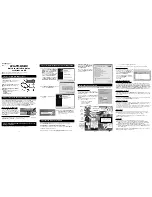
Figure 4-7 Keyboard Control Panel removal
Refer to figure “Keyboard Control Panel removal” for details.
1.
Remove back- and front cover as described earlier.
2.
Remove the fixation screws [1].
3.
Take out the panel assembly and release the connector.
When defective, replace the whole unit.
4.3.5
Power Supply Switch
Figure 4-8 Power Supply Switch removal [1/2]
Figure 4-9 Power Supply Switch removal [2/2]
Refer to figure “Power Supply Switch removal” for details.
1.
Remove back- and front cover as described earlier.
2.
Remove the fixation screws [1] from the rim and remove it.
3.
Now the clips that hold the power switch can be released
via the backside of the switch.
When defective, replace the whole unit.
4.3.6
Speaker Panel
Figure 4-10 Speaker Panel removal
Refer to figure “Speaker Panel removal” for details.
1.
Unplug the connector [1] from the speaker panel.
2.
Remove the fixation screws [2].
3.
Take out the panel.
When defective, replace the whole unit.
4.3.7
Small Signal Panel (SSB)
Refer to figures “SSB Connector Plate” and “SSB” for details.
1.
Remove the screws [1] securing the connector plate.
2.
Do NOT forget
to unplug the LVDS connector [2] from the
SSB.
Important:
Be careful, as this is a very fragile
connector!
3.
Remove the ground cable screw [3].
4.
Unplug the other connectors [4] from the SSB.
5.
Remove all fixation screws [5] securing the SSB.
6.
Lift out the SSB.
When defective, replace the whole unit.
Notes:
•
Pay special attention to the EMC foam on the SSB
shielding. These must be replaced in their initial positions
during set re-assembly.
Figure 4-11 SSB Connector Plate
I_17540_006.ep
s
2
8
010
8
1
1
1
I_17540_005.ep
s
2
8
010
8
1
1
1
1
I_17540_00
8
.ep
s
2
8
010
8
I_17540_004.ep
s
2
8
010
8
1
2
2
2
I_17540_009.ep
s
2
8
010
8
1
1
1
1
1
1
1 1


