Published by Philips Consumer Lifestyle
29
|
39
For internal use only
Document No. : CSW-07-081-18056
GC8702
–
GC8755 / HI8700 / RI8735
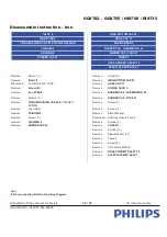
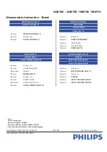
Disassemble Instruction - Iron
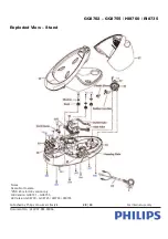
INLAY 9
IRON BOTTOM CAP 23
IRON PCBA 6
HOSE CLIP 13
TRIGGER SPRING CAP 22 & TRIGGER SPRING
DOSING HEAD 2
TRIGGER 8
RUBBER CAP - THERMISTOR 26
HOUSING 4
RUBBER CAP - FUSE 27
RUBBER CAP 24
COVER 3
HOSE CORD MTD ASSY 28
SOLEPLATE MTD ASSY 1
Remove
Screw ( A )
Remove
Screw ( E )
Remove
INLAY 9
Remove
IRON BOTTOM CAP 23
Disconnect
Connectors from PCBA
Remove
HOSE CLIP 13
Remove
Screw ( B )
Remove
DOSING HEAD 2
Remove
Iron PCBA 6
Remove
RUBBER CAP - THERMISTOR 26
Remove
Screws ( C )
Remove
RUBBER CAP - FUSE 27
Remove
TRIGGER SPRING CAP 22 &
TRIGGER
SPRING
Remove
Screw ( F )
Remove
Led Holder
Remove
Screw ( G )
Remove
TRIGGER 8
Remove
Plastic Washer
Remove
Screw ( D )
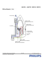
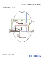
Disconnect All Wires, Hose & Tube #
Remove
HOUSING 4
Remove
Screws ( L )
Remove
RUBBER CAP 24
Remove
COVER 3
Remove
Screws ( H )
Remove
Plastic Washer (2x)
Remove
Chassis
Remove
Screw ( K )
Remove
Cord Clamp Molded
Remove
HOSE CORD MTD ASSY 28
Remove
SOLEPLATE MTD ASSY 1
Notes:
# For reconnection, Refer to the wiring Diagram


