background image

 
User Manual 


Philips MultiOne 

© Philips Lighting B.V.  2014  


Page 60 / 81 


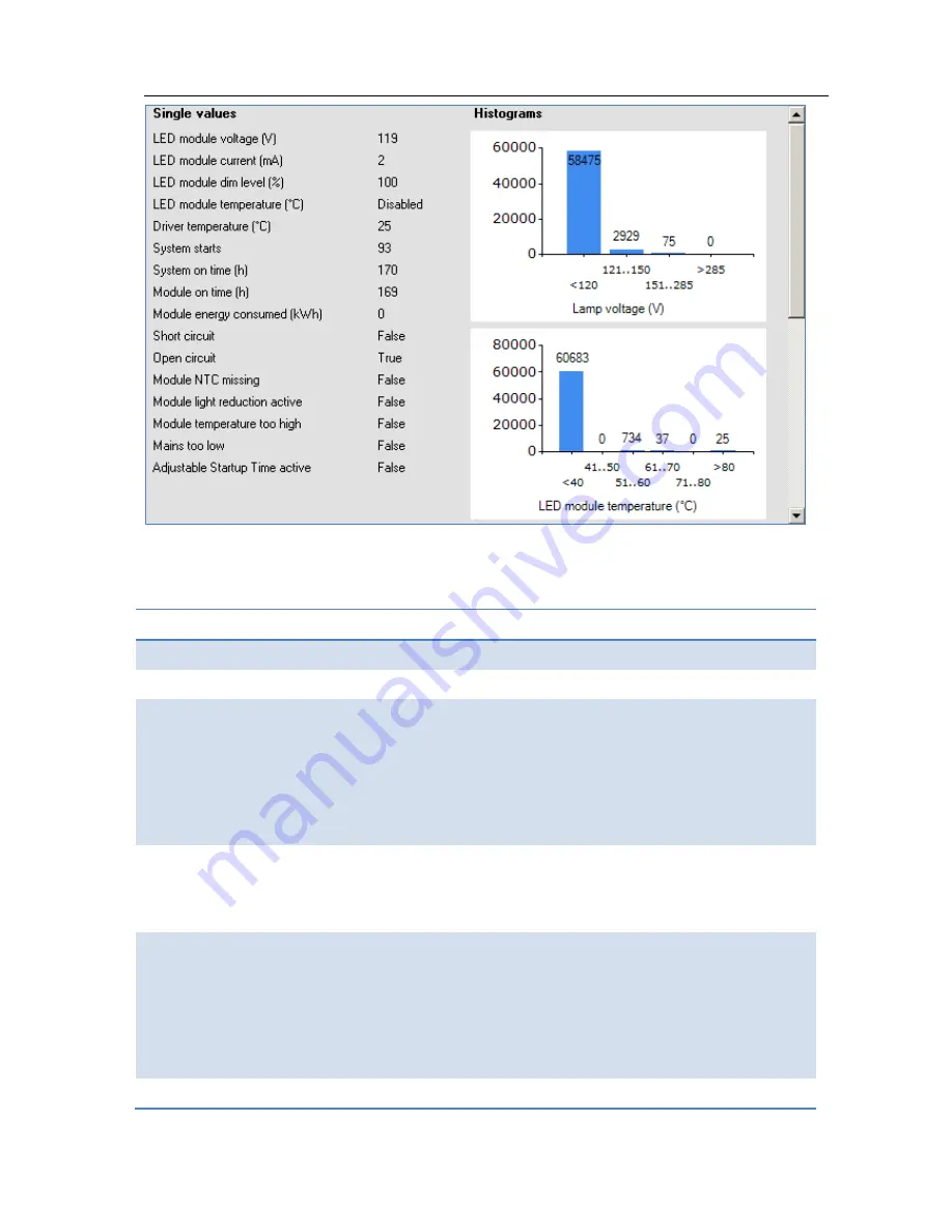
A brief explanation of all LED diagnostics is given below. 

Table 2 LED diagnostics 

Diagnostic 

Description 

LED module voltage (V) 

Represents the output LED module voltage.


LED module current (mA) 

Represents the output LED module current 

LED module dim level (%) 

Represents the current dim level set by the LED 
driver. Takes into account all factors that can 
influence dimming like Constant Light Output, 
Module Temperature Protection, all dimming 
interfaces etc.  

LED module temperature (ºC)  Represents the LED module temperature. Available 

only when Module Temperature Protection is 
selected and an NTC value is selected. 

Driver temperature (ºC)


Represents the internal driver temperature. It does 
not represent T

case

 of the driver. Though there is a 

correlation between T

case

 and internal driver 

temperature, the difference can vary depending on 
current setting of driver.  

System starts 

Represents the number of times the LED driver is 

Summary of Contents for MultiOne

Page 1: ...MultiOne User manual This manual has been updated for MultiOne version 2 6 5 Philips Lighting B V 2014 ...

Page 2: ...n plugged into a device can calibrate ALL the different functions required by any lighting solution Creating the perfect lighting solution has been made very easy with Philips MultiOne With MultiOne you can configure all features that are supported by a Philips device A feature typically belongs to one or two product groups LED Indoor Outdoor HID or FLUO but this does not mean that every device fr...

Page 3: ... interface 14 9 Working with the Philips LCN8600 MultiOne interface USB2DALI 15 9 1 The main application window 15 9 2 Managing the DALI network 15 9 2 1 Identifying devices 15 9 2 2 Selecting devices for communication 16 9 2 3 Managing user defined groups 17 9 2 4 Managing groups 18 10 Working with the Philips LCN8650 MultiOne interface USB2ZigBee 20 10 1 The main application window 20 10 2 Conne...

Page 4: ...ce properties 28 12 2 Communicating with a device 28 12 3 Configuring device features 29 12 3 1 1 10V min dim level 31 12 3 2 ActiLume General 31 12 3 3 ActiLume Mode 32 12 3 4 ActiLume Scene 32 12 3 5 ActiLume Wireless General 33 12 3 6 ActiLume Wireless Mode 34 12 3 7 Active Cooling 34 12 3 8 Adjustable Light Output 35 12 3 9 Adjustable Output Current 36 12 3 10 Adjustable Startup Time 36 12 3 1...

Page 5: ...ltaneously 55 12 8 Configuring multiple DALI devices consecutively 56 12 8 1 MultiOne Basic 56 12 8 2 MultiOne full version 56 12 9 Offline feature configuration preparation 57 12 10 Accessing diagnostics 57 12 11 Sending DALI commands 61 12 12 Querying devices 62 12 13 Working with DALI command scripts 63 12 14 The logging window 65 12 15 Setting preferences 67 12 16 Manually selecting the USB2DA...

Page 6: ...g of errors when reading from a device 71 12 20 3 Reporting of errors when entering incorrect values in a feature 71 12 21 Troubleshooting 72 13 Keyboard shortcuts 74 14 Software Update 75 15 Copyright 77 16 Disclaimer 78 17 Limitations of damages 79 18 List of tables 80 19 Index 81 ...

Page 7: ...ptop with Microsoft Windows XP SP3 Windows 7 Windows 8 or 8 1 USB 2 0 ports o Two free USB 2 0 ports for use with USB2DALI interface o One free USB 2 0 port for use with USB2ZigBee interface o One free USB 2 0 port for use with SimpleSet interface At least 30 MB of free disk space Microsoft NET Framework 3 5 SP1 download here for offline installation ...

Page 8: ... txt document The MultiOne installation file is the installer for the full version of MultiOne This document applies to this version of the software The MultiOne Workflow installation file is the version of MultiOne which is meant to be used in a production environment To install the software launch the installer for the desired version and follow the instructions on your screen The installation w...

Page 9: ... or SimpleSet has been connected to your computer When upgrading the Windows Operating System make sure the connection settings are correct when using MultiOne again 5 2 DALI Lighting applications with DALI devices can be seriously affected by the presence absence of the DALI short address Make sure the DALI short address is as you expect after finishing working with MultiOne ...

Page 10: ...USB2DALI interface status is indicated by three LED s located near the mini USB connector The USB2DALI interface is supplied with a USB cable that can supply the DALI network with up to 220mA It is advised to only use the supplied cable in order to assure correct functioning of the USB2DALI interface Safety Class II double insulated DALI open circuit voltage when power supply enabled 15V mini USB ...

Page 11: ... LCN8650 MultiOne interface USB2ZigBee USB2ZigBee interface is an USB dongle which interfaces between the PC and the ZigBee devices 6 3 SimpleSet The Philips LCN9600 MultiOne interface SimpleSet SimpleSet interface is an USB device which interfaces between the PC and the SimpleSet devices ...

Page 12: ... tasks you would like to perform The application window also has links to the documentation One of the modes is Single device programming This mode simplifies some parts of the device configuration workflow when only one device has been connected Single device programming is discussed in detail in chapter 12 6 If you know that you will mostly perform the same tasks in the future you can select Rem...

Page 13: ...User Manual Philips MultiOne Philips Lighting B V 2014 Page 13 81 You can always go back to the Application Mode Selector by selecting View Application Mode Selector from the main application window ...

Page 14: ... the Application Mode Selector you must select the interface USB2DALI USB2ZigBee or SimpleSet to work with First select the protocol DALI ZigBee or SimpleSet when needed also indicate the selected interface and port This protocol can always be changed later by going to the Tools Connection settings ...

Page 15: ...ne of the DALI connectors of the USB2DALI interface 9 1 The main application window If in the Application Mode Selector screen All is selected as application mode the program will start as follows A more thorough explanation on how to communicate with devices can be found in chapters 12 2 12 11 12 13 12 12 and 12 3 of this manual 9 2 Managing the DALI network The Network panel is used to manage th...

Page 16: ...s are erased and new short addresses are re assigned to all connected devices This procedure ensures that all devices have a short address and that there are no duplicate short addresses After commissioning or scanning the network the list of identified devices is shown in the Network 9 2 2 Selecting devices for communication After having commissioned or scanned the network the Network shows all d...

Page 17: ...hoose Actions Add user defined group A new group is created with a default name but it can be renamed by clicking it once To add a device to a user defined group right click the device select Add to custom group and select one of the available user defined groups Alternatively the device can be dragged onto the desired user defined group to add it to that group To immediately add a device to a new...

Page 18: ...ore comprehensive than user defined groups The important difference is that with DALI grouping information is stored in the devices themselves Therefore DALI grouping is more permanent than user defined grouping By clicking on a device you will make that particular device the active one meaning that all actions will be performed on this device only and will be ignored by all other devices The opti...

Page 19: ... remove device from current group Besides selecting a single device for communication it is also possible to communicate with a group of devices The options are With a right click on a group you can o Identify the devices in the group o Configure add remove multiple devices to from the group o Clear group remove the devices from the group The number of devices in a DALI group is limited to 64 ...

Page 20: ...rk The Network panel is used to manage a connected ZigBee network A number of tasks can be performed in the Network panel each of which is detailed below 10 2 1 Identify devices The ZigBee devices and networks in the area of the USB2ZigBee interface are not automatically known To find devices and networks in the area press Connect to network MultiOne scans for an open network in the area and conne...

Page 21: ...evice or network only and will be ignored by all other devices or networks With a right click on a device you can Identify the device 10 3 Advanced commissioning To commission a ZigBee network right click the Network panel and choose Enable advanced commissioning The Network panel switches to a different view making it possible to manage ZigBee networks 10 3 1 Identify devices Press Scan area to s...

Page 22: ...face o Open network to add more devices 10 3 3 Managing zones Once you have scanned the area and found devices and networks in range it is possible to scan a specific network for zones Select the Zones tab select the Network and press Scan zones After having scanned the network the Zones tab shows the found devices and zones within the specified network By clicking on a device or zone you will mak...

Page 23: ...23 81 o Remove the device will become unassigned If the zone becomes empty the zone will be removed With a right click on a zone you can o Identify the zone o Configure add remove multiple devices to from the zone If other zones become empty they will be removed ...

Page 24: ...User Manual Philips MultiOne Philips Lighting B V 2014 Page 24 81 o Remove zone the zone will be removed and the devices will become unassigned ...

Page 25: ...lows 11 2 Scanning a SimpleSet device The Network panel is used to manage the scanned SimpleSet devices A number of tasks can be performed in the Network panel each of which is detailed below 11 2 1 Identifying devices The SimpleSet device near the SimpleSet interface is not automatically known by MultiOne To get the device press Scan for device a pop up will appear indicating the device must touc...

Page 26: ...User Manual Philips MultiOne Philips Lighting B V 2014 Page 26 81 until the scan has completed The scanned device will be shown in the Network panel ...

Page 27: ...device you will make that particular device the active one meaning that all actions will be performed on this device only and will be ignored by all other devices 11 4 Starting communication In order to communicate with a SimpleSet device the device has to touch the SimpleSet interface Before starting the communication MultiOne will show a pop up when the device is not near the SimpleSet interface...

Page 28: ...en clicking Read When the Device features tab is active both Read and Write actions are available Reading and writing will always take a few seconds Operation progress is shown on the status bar of the main application window On the Device features tab per feature progress is shown on each of the feature selection tabs When all information has been successfully read or written a green tick mark wi...

Page 29: ... Each feature has its own tab For most devices a Summary tab is available as well To make sure that the feature information in the Device features tab corresponds to the selected device click Read on the toolbar To make sure that the feature information is stored in the selected device click Write on the toolbar For both Read and Write status icons will be shown when a feature is being read or wri...

Page 30: ...ou will find an overview of all supported device features in alphabetical order Features typically belong to one or two product groups LED HID or FLUO but this does not mean that every device belonging to a certain product group will automatically support all of its features listed here For an overview of supported device features see Supported features ...

Page 31: ...p LED Description Use this feature to set the minimum dim level when using 1 10V dimming interface Usage Use the slider or the text field to select a value The value represents the light level 12 3 2 ActiLume General Product group CONTROL Description Use this feature to configure general ActiLume settings ...

Page 32: ...ettings that apply to the system s modes For ActiLume DALI gen2 up to 16 modes are shown each of which has its own feature tab on the left hand side Use the ActiLume Mode feature to configure settings for each individual mode Usage Use the various drop down boxes check boxes and text fields to make a configuration Click the Reset to factory defaults button to reset the current mode to the factory ...

Page 33: ... Use the ActiLume Scene feature to configure settings for each individual scene Usage Use the various check boxes and text fields to make a configuration Click the Reset to factory defaults button to reset the current scene to the factory defaults Please refer to the ActiLume DALI gen2 Application Guide for further details 12 3 5 ActiLume Wireless General Product group CONTROL Description Use this...

Page 34: ...n Use this feature to configure ActiLume Wireless settings that apply to the system s modes For ActiLume Wireless up to 32 modes are shown each of which has its own feature tab on the left hand side Use the ActiLume Wireless Mode feature to configure settings for each individual mode Usage Use the various drop down boxes check boxes and text fields to make a configuration Please refer to the ActiL...

Page 35: ...he LED module should be reduced The customer can specify the temperature limits to make sure the fan output level is kept as low as possible and will only increase when needed so the audible noise is reduced Usage Drag the points or the lines in the resulting graph to adjust the configuration Alternatively use the table to enter values directly NOTE For a detailed technical description of the char...

Page 36: ... Current AOC feature to adjust the output current to a desired optimum value You can create a virtual lamp with output different than what the standard wattages offer Usage The current can be set in two ways Select the External Rset check box Adjustment of the output current is not configured using MultiOne but the value of an external resistor adjusts the output current OR Use the slider or the t...

Page 37: ...utput of a lamp by adjusting the mains voltage of the device Usage Select the Enable check box to use this feature note that LED devices do not have this check box Drag the points or the lines in the graph to create the desired configuration Alternatively use the table to directly enter values NOTE For a detailed technical description of the characteristics of the device model like constraints and...

Page 38: ...ul when replacing the HID lamp The Constant Light Output feature for LED devices will show the following window Description The lumen output of a LED module usually decreases over its lifetime To compensate a schedule can be created that gradually increases the lamp s power level over time Usage Select the Enable check box to use this feature Click the New button to create a default schedule or cl...

Page 39: ...r of burning hours is divided Initial dimlevel the power level that is the starting point at 0 burning hours Final dimlevel the power level at the end of the defined lifetime the value given for maximum number of burning hours After clicking Finish a CLO schedule will be created using linear interpolation of the provided values Drag the points or the lines in the resulting graph to adjust the conf...

Page 40: ...s feature has the following parameters Normal level Light level to be set when presence sensor detects activity Background level Low light level to be set when no presence is detected after the fade time Delay time The time from the moment the sensor has switched off and the moment the device will start to fade to background level Fade time The time used to fade from normal level to background lev...

Page 41: ...pDim LineSwitch When DALI has been selected an additional setting appears with which the dimming behavior can be set Options are Logarithmic and Linear dimming curves Usage Use Dimming Interface to select the desired dimming interface Product group FLUO LED Description Use the Dimming Interface feature to select the dimming interface for the device Usage The available dimming interfaces are stored...

Page 42: ...nce for timekeeping When the Time based check box is selected the reference point is the moment when the mains are switched on Selecting the Time based check box changes the graph and removes its dotted midnight line Note that not all devices support Time based Dynadimmer Midnight shift the midnight point depends on the geographical location Enter the midnight shift in minutes or use the midnight ...

Page 43: ...ving should be dealt with or not You have two choices for calculation of midnight shift If your location is available in the location list you can use it Some locations are not listed For those unlisted locations use the geographical coordinates to calculate the correct midnight shift Click OK to save result of your calculation as the new midnight shift Note that clicking OK is not directly saving...

Page 44: ...mp is activated To see the physical min level of the selected lamp in the graph click Read on the toolbar 12 3 15 2 Location or custom location For some device models only the midnight point offset is stored in the device and NOT the custom location In those cases the location information and the custom location is only used to calculate the midnight point offset After reading out the device Multi...

Page 45: ...disabled during this DC Emergency operation Usage Select the Enable check box to use this feature Use the slider or the text field to select a value The value represents the arc power level when in DC Emergency mode the label on the right gives the approximate light level percentage Select the Allow dimming check box to allow dimming when in DC Emergency mode ...

Page 46: ...umber of hours specified as End Of Life This feature uses the same burning hours counter as the Light Source Operating Hours and Constant Light Output features Usage Select the Enable check box to use this feature Use the slider or the text field to select a value The value represents the guaranteed lifetime in hours 12 3 18 Energy Meter Product group FLUO HID Description Use this feature to get a...

Page 47: ...o select a value The value represents the maximum arc power level for dimming the label on the right gives the approximate light level in percent Alternatively select the Use default check box to use the default value Burn in time use the slider or the text field to select a value The value represents the time in minutes during which the burn in level is active Alternatively select the Use default...

Page 48: ... driver off for a few seconds After switching is on again the selected lamp is activated 12 3 21 Light Source Operating Hours Product group LED Description Use this feature to manually set or reset the number of operating hours for the LED module This is useful when replacing the LED module thereby resetting features like Constant Light Output and End Of Life indication Usage Use the slider or the...

Page 49: ...V level Use the slider or the text field to select a value The value represents light level to be set when low voltage is detected on the mains Fade on time Use the slider or the text field to select a value The value represents the fade on time to be used Switch off delay time Use the slider or the text field to select a value The value represents the switch off delay time to be used Fade off tim...

Page 50: ...im level in percent The dim level will be used during the dim period 12 3 24 Min Dim Level Product group LED Description This feature provides an interface for setting the min dim level of a device Usage Select the Enable check box to use this feature Use the slider or the text field to select a value The value represents the min dim level in percentage ...

Page 51: ...evel the lamp will switch off completely Usage Select the Enable check box to use this feature Drag the points or the lines in the resulting graph to adjust the configuration Alternatively use the sliders to changes values directly Based on the device model the feature is shown in either temperature degrees Celsius or resistance values in Ohm NOTE For a detailed technical description of the charac...

Page 52: ...the Enable check box to use this feature 12 3 27 Touch and Dim Product group FLUO LED Description This feature defines the startup behavior of a touch and dim controlled device after a power failure during dimming Usage When the Use last known level check box is selected the device will start up at the last known dim level that was used during dimming If this is not checked the power on level can ...

Page 53: ... been entered for all the features of this device As the features are different per product group the summary is also different The features cannot be changed on the Summary tab 12 5 Saving and opening a feature configuration file To save and open a feature configuration file the Device features tab must be active Feature configurations can be saved to a file for later use To do so first select th...

Page 54: ...eature configurations are stored in the file This means that a file made for a certain device can be read into the Device features tab for a different device MultiOne attempts to read as many feature configurations as possible Example a feature configuration file exists that was made for device D1 which has features AOC CLO and MTP A different device D2 has features AOC Energy Meter and Touch and ...

Page 55: ... be configured at the same time The procedure to simultaneously configure multiple devices of the SAME TYPE AND VERSION is as follows Note this method will not work with MultiOne Basic 1 Connect maximum 64 devices of the SAME TYPE AND VERSION in parallel to the DALI connectors of the USB2DALI interface 2 Connect the USB2DALI interface to the USB port both black and red USB plugs USB A 3 Connect th...

Page 56: ...feature configuration file 8 Select the Commands tab 9 At Data field enter 255 click the Short Addr button See NOTE This removes the short address in the network the short address is shown as broadcast 10 Select the Device features tab 11 Click Write on the toolbar 12 Replace device 13 Click Write on the toolbar 14 Replace device 15 Etc 12 8 2 MultiOne full version 1 Connect one device 2 Connect t...

Page 57: ...election and click OK An item called Virtual devices appears in the Network Expand it by clicking the sign to see the list of virtual devices Note that virtual devices do not have a short address and MultiOne will show Broadcast on the location of the short address Virtual devices can only be addressed using broadcast commands Select a virtual device and select the Device features tab The device f...

Page 58: ...D driver attempted to ignite the lamp since last lamp replacement a Failures Total number of failures detected by the HID driver Total energy consumed Total energy consumed by the HID driver Energy consumed resettable Wh Energy consumed since last user reset 24H reset expirations HID driver was operating for more than 24 hours any failures blocking driver to operate the lamp are cleared Thermal Gu...

Page 59: ...on lamp type Cycling lamp failures Cycling of the lamp extinguished for more than N times subsequently since last lamp replacement where N depends on lamp type a Extinguished failures driver Detection of an extinguished lamp Extinguished failures lamp Detection of an extinguished lamp since last lamp replacement a Mains high failures Mains voltage level detected that was too high to continue opera...

Page 60: ...nt all factors that can influence dimming like Constant Light Output Module Temperature Protection all dimming interfaces etc LED module temperature ºC Represents the LED module temperature Available only when Module Temperature Protection is selected and an NTC value is selected Driver temperature ºC Represents the internal driver temperature It does not represent Tcase of the driver Though there...

Page 61: ...on the LED module Available only when Module Temperature Protection is selected and 10k NTC is selected Missing NTC flag will not be activated if 15k 390 Ω NTC is selected Module temperature reduction active This indicates light level reduction due to module temperature being active Module temperature too high This indicates whether the LED module temperature exceeds 90 ºC causing module to turn O...

Page 62: ... in the Commander pane and finally click the Send button To send a DALI command to a specific address or group select the corresponding device or group in the Network Configuration commands To manually set or get the so called DTR Data Transfer Register values of the device use the buttons in the left part of this pane To use the actual DTR value of the device with a number of DALI commands use th...

Page 63: ... Query tab corresponds to the selected device click Read on the toolbar 12 13 Working with DALI command scripts To run a series of DALI commands a script can be created in the Scheduler tab This script can be executed any number of times Furthermore it is possible to save the script to a file for easy reuse ...

Page 64: ...o add a command to the schedule click the CMD button The command is added to the schedule and it is automatically highlighted On the Selected item pane choose the desired DALI command and settings By selecting the Start time check box and providing a time this command will be sent at an exact moment in time Alternatively commands can be sent relative to each other Select the Delay check box and pr...

Page 65: ...ng the Delete button To start pause or stop a schedule playback use the Play Pause and Stop buttons To save a schedule to file for later use click the disk icon on the toolbar Alternatively select File Save or File Save As Choose a location a filename and click Save The schedule has now been saved To open a previously stored schedule click the folder icon on the toolbar Alternatively select File O...

Page 66: ...User Manual Philips MultiOne Philips Lighting B V 2014 Page 66 81 The name of the feature or the actual DALI command Result Result of the communication ...

Page 67: ...hoose an application mode based on the tasks you would like to perform You can disable this screen by clearing the Show application mode selector on startup checkbox Changing this settings only takes effect one MultiOne is restarted Scan network automatically on startup By checking this checkbox MultiOne will automatically initiate a network scan on startup Changing this settings only takes effect...

Page 68: ...ultiOne will automatically check for updates and if available download and install them automatically Automatic Check download only MultiOne will automatically check for updates and if available download them The user then has to agree to let MultiOne update itself Automatic Check only MultiOne will automatically check for updates and notify the user if a new version is available The user can then...

Page 69: ...User Manual Philips MultiOne Philips Lighting B V 2014 Page 69 81 In the pop up window it is then possible to select the desired port ...

Page 70: ...al power supply you can do so using the option Tools Power supply 12 18 Supported features The table below gives an overview of all features that are supported by MultiOne and to which product groups they apply Table 3 Supported features Device feature Product group LED HID FLUO CONTROL Indoor Outdoor 1 10V min dim level x ActiLume General x ActiLume Mode x ActiLume Scene x ActiLume Wireless Gener...

Page 71: ... www philips com Actilume 12 20 Error handling 12 20 1 Reporting and correction of errors warnings when reading from a feature configuration file When after opening a feature configuration file incorrect parameters are detected MultiOne tries to correct these parameters for the selected virtual device When a correction is made a red border will be shown In cases when no logical correction can be m...

Page 72: ...ed short address Click OK to program the short address into the device Problem I would like to remove the short address of a device Solution First scan the network for devices Right click the device whose short address you would like to remove and select Reset short address You will be informed that the short address was reset Problem I would like to configure the special features of the connected...

Page 73: ...User Manual Philips MultiOne Philips Lighting B V 2014 Page 73 81 For FLUO drivers visit www philips com HFR Intelligent For controls visit www philips com Actilume ...

Page 74: ...ion file Not supported Ctrl S Save a feature configuration file Save Not supported Ctrl Shift S Save a feature configuration file Save As Not supported Alt F4 Exit MultiOne The Action menu Working with devices Ctrl D Scan network Scan area Ctrl Q Commission Not supported Ctrl R Read from current device Not supported Ctrl W Write to current device Not supported The Tools menu Ctrl M Open the Applic...

Page 75: ...ssibility to update itself to a newer version This can be done either automatically or manually and can be set in the preference window see the Setting Preferences for more info If the preference is set to Manual then the user can check for an update on MultiOne by selecting Help Check for updates option ...

Page 76: ...lp menu will show if a new version is available The user can then decide to continue downloading updating by either using the update status or the Help menu to carry on After downloading the update status will inform the user to restart to continue Restarting MultiOne will install the update A successful update of MultiOne will be shown in the update status ...

Page 77: ...ion may be reproduced transmitted transcribed stored in a retrieval system or translated into any language or computer language in any form or by any means electronic mechanical magnetic optical chemical manual or otherwise without prior written permission from Philips Brands and product names are trademarks or registered trademarks of their respective companies ...

Page 78: ... with regard to this material including but not limited to the implied warranties of merchantability and fitness for a particular purpose Philips assumes no responsibility for any error that may appear in this document Philips makes no commitment to update nor to keep current the information contained in this document ...

Page 79: ... consequential damages including damages for loss of business loss of profits or the like whether based on breach of contract tort including negligence product liability or otherwise even if the vendor or its representatives have been advised of the possibility of such damages and even if a remedy set forth herein is found to have failed its essential purpose ...

Page 80: ...anual Philips MultiOne Philips Lighting B V 2014 Page 80 81 18 List of tables Table 1 HID diagnostics 58 Table 2 LED diagnostics 60 Table 3 Supported features 70 Table 4 Product specific Philips web sites 71 ...

Page 81: ...0 66 Constant Light Output 37 38 44 46 57 67 Corridor Mode 39 67 DC Emergency 43 67 Dimming Interface 40 67 Dynadimmer 40 41 67 End Of Life indication 44 46 67 Energy Meter 44 52 67 Lamp Burn in 45 67 Lamp Selection 43 45 67 Light Source Operating Hours 44 46 67 LineSwitch 40 46 67 LumiStep 47 67 Min Dim Level 47 67 Module Temperature Protection 49 57 58 67 Network 16 17 21 22 23 26 27 28 52 53 54...

Reviews: