A
B
C
D
E
F
H
G
I
K
J
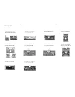
Disassembly Diagram
3-1
3-1
A.Turn-on electrical source to open the CD tray;
after that,turn-off electrical source.uses ironbound
thimble prize up the CD door(see the sign A).
E.Loosen screws to remove CD front cabinet.
(see the sign E&F: screw 3x5 BMTT plate
/ screw 3x5 FMTT).
J.Loosen nut to remove the display board.
(see the sign J).
K.Loosen screws to remove the display board.
(see the sign K: screws 2.6x8 PA plate).
G.Loosen screws to remove the decoder board.
(see the sign G: screw 3x10 PBH plate
& screw 3x6 PMTT plate).
H.Loosen screws to remove the back panel.
(see the sign H: screw 3x6 PMTT plate).
I.Loosen screws to take out the decoder
board.(see the sign H: screw 3x5 BM plate).
B.Loosen screws of the top cover both sides
(see the sign B: screw 3x6 TMTT plate)
C.Loosen screws of the top cover back side
(see the sign C: screw 3x6 PMTT plate)
D.Loosen screws to remove the CD tray
(see the sign D: screw 3x10 PWA plate)
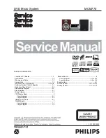
Summary of Contents for MCM770
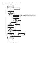
Page 9: ... 0DOIXQFWLRQ IROORZ FKHFN FKDUW ...
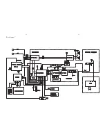
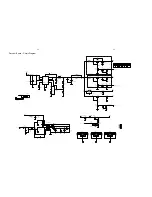
Page 11: ...4 1 4 1 Block Diagram ...
Page 12: ...86 2 5 9 2 5 32 5 6 7 9 6 03 2 5 72 63 5 LULQJ LDJUDP ...
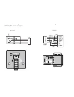
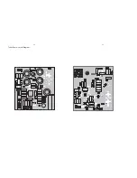
Page 14: ...5 2 5 2 VFD Display Board Layout Diagram ...
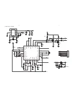
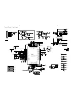
Page 17: ...7XQHU RDUG D RXW LDJUDP ...
Page 22: ...8 5 8 5 Decoder Board Layout Diagram Top ...
Page 23: ...8 6 8 6 Decoder Board Layout Diagram Bottom ...
Page 24: ...9 1 9 1 EXPLODE VIEW ...

