background image

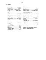
AMPLIFIER

Rated Output Power ........................  ..2 x 75W RMS

Signal-to-noise ratio .................................

 65 dBA

Frequency response ......... 40Hz + 3dB+/-3 20KHz 

Aux Input ......................................0.5V RMS 47kohm

DISC

Laser Type .......................................... Semiconductor

Disc Diameter ............................................ 12cm/8cm

Support Disc ......................................................DVD,

DVD-R,DVD-RW,DVD+RW,CD-DA,MP3,CD-RW

Audio DAC ....................................... 24Bits / 44.1kHz

Total Harmonic Distortion ..................... <0.5%(1kHz)

Frequency Response ..........40Hz + 0.5dB+/-2 20KHz

S/N Ration ....................................................

•G

BA

TUNER

FM Tuning Range ............................. 87.5 – 108 MHz

Tuning grid ............................................100K/50KHz

Sensitivity

– Mono, 50dB S/N Ratio ..................................... 5u V

– Stereo, 50dB S/N Ratio ................................ 100uV

Selectivity ........................................................ >28dB

Image Rejection .............................................. >25dB

Total Harmonic Distortion ................................... <1%

Signal to Noise Ration .................................. >65dBA

SPEAKERS

Speaker Impedance ................................................ 4ohm

Speaker Driver, base ................................................5 1/4"

Speaker Driver, tweeter ....................................B U Z Z E R

Frequency Response ...................40Hz + 3dB+/-3 20KHz

GENERAL INFORMATION

Total Output power .....................................   1 5 0 W  RMS

AC Power ..................................... 220-230 V / 50Hz/60Hz

Operation Power Consumption ................................. 85W

Standby Power Consumption ..................................... <4W

Eco Standby Power Consumption ..............................<1W

Headphone Output ................................ 2X15mW 32ohm
USB Direct ...................................................... Version 1.1

Dimensions

– Main unit (w x h x d) ............................275x126x250mm

– Speaker box (w x h x d) ....................186x300x222.5mm

Weight

With Packing

................................................... 16.5 KG

Main Unit .............................................................. 5.0KG

Speaker box .................................................... . 4.5x2KG

Specifications and external appearance are
subject to change without notice.

1-2

Specification

Summary of Contents for MCD 906

Page 1: ...2 Decoder Board 11 Disassembly Diagram 3 1 Block Diagram 4 1 Wiring Diagram 4 2 VFD Display Board 5 Circuit diagram 5 1 Layout diagram 5 2 Prepositive Board 6 Circuit diagram 6 1 Layout diagram 6 2 AMP Board 7 Headphone Button AUX Board Diagram 8 Circuit diagram 7 1 Layout diagram 7 2 TUNER Board 10 Circuit diagram 10 1 Layout diagram 10 2 Circuit diagram 11 1 to 11 8 Layout diagram 11 9 to 11 10 ...

Page 2: ...ponent Lever Repair M Module Lever Repair Used 55 55 58 58 61 61 79 79 93 93 94 94 96 96 98 98 37 37 12 12 05 05 Feature diffrence RDS TDS VOLTAGE SELECTOR ECO STANDBY DARK M M M M M M M M M M M M Type Versions MCD906 TUNER BOARD PREPOSITIVE BOARD DISPLAY BOARD HEADPHONE BOARD DECODER BOARD AUX BOARD AMP BOARD SCART BOARD 12 05version ECO POWER BOARD 12 05version VOLTAGE SELECTOR BOARD 98version L...

Page 3: ...ity 28dB Image Rejection 25dB Total Harmonic Distortion 1 Signal to Noise Ration 65dBA SPEAKERS Speaker Impedance 4ohm Speaker Driver base 5 1 4 Speaker Driver tweeter B U Z Z E R Frequency Response 40Hz 3dB 3 20KHz GENERAL INFORMATION Total Output power 1 5 0 W RMS AC Power 220 230V 50Hz 60Hz Operation Power Consumption 85W Standby Power Consumption 4W Eco Standby Power Consumption 1W Headphone O...

Page 4: ...15kHz e g 7122 707 48001 LF Voltmeter e g PM2534 DUT S N and distortion meter e g Sound Technology ST1700B Frame aerial e g 7122 707 89001 Tuner AM MW LW To avoid atmospheric interference all AM measurements have to be carried out in a Faraday s cage Use a bandpass filter or at least a high pass filter with 250Hz to eliminate hum 50Hz 100Hz RF Generator e g PM5326 Ri 50 Bandpass 250Hz 15kHz e g 71...

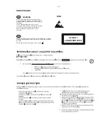
Page 5: ...ng make sure that you are connected with the same potential as the mass of the set via a wrist wrap with resistance Keep components and tools also at this potential ESD CLASS 1 LASER PRODUCT GB Safety regulations require that the set be restored to its original condition and that parts which are identical with those specified be used Safety components are marked by the symbol Lead free ...

Page 6: ...ET OK check playability N Y playability ok check playability check playability return set Customer complaint CD related problem fast lens cleaning 1 2 3 For flap loaders access to CD drive possible cleaning method 4 is recommended INSTRUCTIONS ON CD PLAYABILITY 1 Exchange CDM 1 4 For description see following pages ...

Page 7: ...obviously caused by a scratched dirty or copy protected CD In case problems remain the customer is requested to contact the workshop directly The lens cleaning method 3 should be mentioned in the addendum sheet The final wording in national language as well as the printing is under responsibility of the Regional Service Organizations 4 LIQUID LENS CLEANING Because the material of the lens is synth...

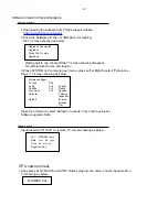
Page 8: ...CHI English Subtitle CHI French Disc menu CHI Spanish Parental Chinese Japanese Default Korean Russian Tjai Upgrade Press PLAY to start Upgrading CPU version check 1 Downloading the software form Philips support website 1 Keep press PLAY PAUSE and STOP buttons plug into the power cord at the same time TV showing as below 2 Put in the Software CD Disc or USB when it is loading the TV screen showing...

Page 9: ... 0DOIXQFWLRQ IROORZ FKHFN FKDUW ...

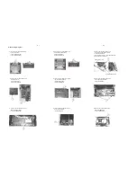
Page 10: ...s 2 6x4BB 2PCS F Loosen screws as below sketch map to remove the Prepositive Board 1 screws 3x6PA 2PCS G Loosen screws as below sketch map to remove the Display Board 1 screws 2 6x6BB 10PCS B Loosen screws as below sketch map to remove the both sides panels 1 screws 3x6PA 6PCS 2 screws 3x10PA 4PCS C Loosen screws as below sketch map to remove the DVD mechanism bracket 1 screws 3x12BA 2PCS 2 after ...

Page 11: ...D5V AC POWER SWITCH POWER STANDBY POWER CONTROL SWITCH 7812 SELENIUM SELENIUM FILTER FILTER AMP DVD CPU5V DVD5V AMC2576 DVD ON OFF DVD POWER SWITCH CONTROL TUNER RIN AUX2 IN AUX1 IN D FL D FR CPU SDA SCL FR FL KEY CONTROL FR FL STANDBY MUTE vs vs vs vs D FL D FR 12AX7 FR FL TL027 FR FL vs vs SELENIUM FILTER FRONT APW7080 12V FM 5V TUNER LIN TUNER RIN TUNER LIN 4 1 4 1 Block Diagram IC201 VFD Displ...

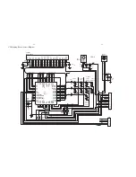
Page 12: ...Wiring Diagram 4 2 4 2 VALVE LAMP BOARD L VALVE LAMP BOARD R BUTTON BOARD DISPLAY BOARD USB BOARD LAMP BOARD LAMP BOARD DECODER BOARD AUX BOARD AMP BOARD PREPOSITIVE BOARD ...

Page 13: ...S5 S6 S7 S8 S9 KS1 KS2 28V 5V S1 S2 C208 104 R202 4 7 0 5 REM 1 GND 2 Vcc 3 S201 REMOTE S10 S11 S12 S13 S14 S15 S16 S17 G11 G10 G1 G2 G3 G4 G5 G6 G7 G8 G9 D202 4148 S3 KS3 R201 4 7 0 5 C201 104 C207 47uF SW201 CH SW203 CH SW204 TU PREV SW207 TU NEXT SW202 STOP SW205 MODE SW206 OPEN CLOCS R211 10K R212 4 7K R213 10K G 1 B 2 A 3 CORD201 CORD C204 103 C203 103 RT A RT B R207 47 C206 47u C205 104 R206...

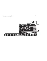
Page 14: ...5 2 5 2 VFD Display Board Layout Diagram ...

Page 15: ...uF 450V C16 1uF 250V Q2A 12AX7 Q2B 12AX7 R59 330K 0 5W C13 104 J 450V 12V R55 8 2K 0 25W R28 47K 0 25W R57 3 3K 0 5W C11 5P R61 150K 0 5W R63 560 0 5W R65 330K 0 5W C15 1uF 450V C17 1uF 250V R52 47K 0 25W GND GND VCC C9 100uF 400V R31 1K R37 680 R67 47K0 25W R66 3 3K0 25W R69 47K0 25W R68 3 3K0 25W OUT L OUT R OUT L OUT R LIN RIN R1 470K Q3 9014 C1 330uF 16V D1 4148 1 2 3 4 CN1 3P 12V GND 1 2 3 4 ...

Page 16: ...Prepositive Board Layout Diagram 6 2 6 2 ...

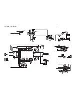
Page 17: ... 104p C305 104p C303 333 28V C307 474 C302 104 R333 240K 28V L O R O DZ2 12V DZ1 12V C1 47uF C2 47uF L IN R IN MUTE R313 1 5K Q300 BC817B R303 2 2K R300 4 7K L303 JRH0349 L304 JRH0349 VSSA2 1 VDDA2 3 VSSD 24 STABL 18 PROT 13 SUB VSSD 19 VDDP2 23 VSSP2 20 BOOT2 22 OUT2 21 OUT1 16 BOOT1 15 VSSP1 17 VDDP1 14 MODE 6 OSC 7 VSSA1 12 VDDA1 10 IN1 8 IN1 9 SGND1 11 SGND2 2 1N2 5 IN2 4 IC300 TDA8920BTH C355...

Page 18: ...7 2 7 2 AMP Board Layout Diagram ...

Page 19: ...JACK801 PH JACK 1 2 3 4 CN801 4P Headphone Board Button Board 1 2 3 4 5 6 CN402 6P 1 2 3 4 5 6 CN401 AUX GND GND AUX1L AUX1R AUX2L AUX2R R405 100 R403 100 R404 100 R402 100 R406 47K R407 47K R400 47K R401 47K AUX Board SW211 SOURCE SW208 STANDBY 1 2 3 4 5 CN1 5P K1 K4 KS1 LED LED1 LED 35 MCD906 01A1 ...

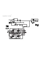
Page 20: ...9 1 9 1 1 2 CN501 2P LED501 LED R501 680 1 2 CN601 2P LED601 LED R601 680 1 2 CN701 2P LED701 LED R701 680 LED702 LED R702 680 VALVE LAMP BOARD L LAMP BOARD VALVE LAMP BOARD R Lamp Board Diagram ...

Page 21: ... S A D S X T N I 2 1 C 4 0 1 2 2 R 0 3 3 8 1 C F u 2 2 V 5 V 0 3 V 0 3 X P M 5 C 4 2 2 4 C 4 2 2 2 Q 4 1 0 9 3 Q 4 1 0 9 4 R K 7 4 5 R K 7 4 3 R M 1 1 R 7 4 3 1 R K 1 4 1 R K 1 1 C F u 2 2 2 C 4 2 2 3 C 4 2 2 2 R M 1 V 5 T U O L T U O R 1 Z D V 6 3 6 R K 7 4 9 1 C V 3 6 F u 7 4 T U O R T U O L D N G S V 5 L C S A D S D N G S 1 2 3 4 5 6 7 8 1 N C P 8 5 L R 0 0 6 4 L R 0 0 6 RFIN 8 R k 8 6 K C O L ...

Page 22: ...Tuner Board Layout Diagram 10 2 10 2 ...

Page 23: ...1uF CB13 0 1uF R3 0 R1 12K CE8 220uF 16V CB11 0 1uF R9 1 2K CE10 47uF 16V MK2 R5 30K L6 FB R12 390 L7 FB R4 100K C2 1uF PP1 2 3 4 5 9 8 7 6 1 2 3 4 5 9 8 7 6 1 MK3 U1 APW7080 1 2 3 4 5 6 7 8 9 VIN EN UGND VCC LX COMP FB GND LXX CB16 0 1uF CB3 0 1uF PP3 2 3 4 5 9 8 7 6 1 2 3 4 5 9 8 7 6 1 D3 IN4001 DIP 1 2 CE72 47uF 16V R2 30K CB12 0 1uF MK4 C3 2200pF R7 2K CB1 0 1uF CE1 100uF 16V L5 FB 600 U4 AZ11...

Page 24: ...1uF CE15 47uF 16V CB21 0 1uF L11 FB Q2 2N3904 2 1 3 R27 150K C8 2200pF R15 10K CON1 H24 SMD0 5 25 26 3 4 6 7 8 9 10 11 12 13 14 15 16 17 18 19 20 21 22 23 24 2 5 1 C6 0 1uF NC R35 20K Q4 2SK3018 1 3 2 R25 680K R29 1 0805 Q3 2SK3018 1 3 2 R14 10K R28 1 0805 CE17 220uF 16V R33 20K R16 10k R20 100 CB20 0 1uF R19 33 R36 0 CE16 47uF 16V CE14 100uF 16V R26 150K R17 100K C10 150pF C7 2200pF C9 150pF R21 ...

Page 25: ...GC IREF AVDD3 AGND DVDA DVDB DVDC DVDD DVDRFIP MA MB MC MD SA SB SC TNI SD TPI MDI1 MDI2 LDO2 LDO1 SVDD3 CSO RFOP RFLVL RFON SGND V2REF V20 VREFO FEO TEO TEZISLV OP_OUT OP_INN OP_INP DMO FMO TROPENPWM PWMOUT1 _ADIN0 TRO FOO AGND18_DMPLL AVDD18_DMPLL USB_DP USB_DM VDD33_USB VSS33_USB PAD_VRT VDD18_USB VSS18_USB USB_XTALO GPIO15 USB_XTALI GPIO14 FG GPIO16 IOA22 GPIO18 DVDD18 IOA2 IOA3 IOA4 IOA5 IOA6...

Page 26: ...CE28 100uF 16V U7 ESMT M12L64164A 7T 1 2 4 12 5 7 9 8 10 46 11 13 15 16 17 18 19 35 22 23 24 25 26 14 41 29 30 31 32 33 34 36 37 38 39 40 43 42 44 52 45 47 49 48 50 51 53 54 20 21 3 6 27 28 VCC DQ0 DQ1 VSSQ DQ2 DQ3 VCCQ DQ4 DQ5 VSSQ DQ6 DQ7 DQML WE CAS RAS CS A11 A10 AP A0 A1 A2 A3 VCC VSS A4 A5 A6 A7 A8 A9 NC CKE CLK DQMH NC VCCQ DQ8 DQ9 VSSQ DQ10 DQ11 VCCQ DQ12 DQ13 DQ14 DQ15 VSS BA0 A13 BA1 A12...

Page 27: ...00pF NC Q37 3904 2 1 3 R86 75 1 R93 150 1 C103 100pF R98 150 1 R81 3 3K R89 3 3K Q13 3904 2 1 3 R102 100 J4 CON2 0 3 NC 1 2 3 R91 150 1 R84 2 2K R87 2 2K CB77 0 1uF Q8 3904 2 1 3 R97 3 3K CE33 22uF 16V R96 75 1 CB73 0 1uF C61 47pF R92 2 2K C54 47pF R99 2 2K L39 FB R246 75 1 C104 1000pF L44 1 8uH C59 330pF L37 1 8uH R83 150 1 C57 47pF Q11 3904 2 1 3 R88 75 1 L41 FB CB78 0 1uF R95 75 1 CB74 0 1uF L4...

Page 28: ...DV33 DV33 D19 1N4148 1 2 R119 1k R121 1K R135 2 2K Q17 2N3906 2 1 3 L45 FB R129 10K R115 1M Q14 2N3904 2 1 3 Q21 2N3906 2 1 3 CB79 0 1uF R123 100K Q15 3904 R133 33 R124 10K Q20 2N3904 2 1 3 R118 10K CE38 10uF 16V D18 4 3V CE37 100uF 16V L46 FB R127 4 7K R120 47K R110 47K CB80 0 1uF R131 2 2K R117 43K R134 4 7K R114 100K C64 100pF R126 680 R109 10K R122 470 0805 R132 2 2K D16 1N4148 1 2 D17 1N4148 ...

Page 29: ...3 TX2 3 TX1 3 TXC 3 TXC 3 HPD 3 TS_DATA2 3 VCC DV33 VCC DV33 D30 NC L48 FB R139 1 5K R137 27K R141 0 D31 NC R242 47 NC CB86 0 1uF NC D25 NC P2 HDMI TYPE A 1 2 3 4 5 6 7 8 9 10 11 12 13 14 15 16 17 18 19 22 21 20 23 Q33 CES2312 NC 1 3 2 D26 NC D21 NC CE40 10uF 16V D22 NC D23 NC CB81 0 1uF D29 1N4148 L49 FB NC D24 NC R136 0 NC R140 0 L47 FB 600 L50 FB NC D27 NC D28 NC R138 1 5K 11 7 11 7 Decoder Boa...

Page 30: ...K C87 220pF R148 47K R187 47K R171 4 7K TP1 CE47 2 2uF 50V TP6 TP12 CE66 1uF 50V TP24 TP13 R237 330 Q22 8550 2 1 3 R155 100 R154 47K CE54 2 2uF 50V C114 1000pF CE43 2 2uF 50V CE41 2 2uF 50V C89 220pF D34 1N4148 1 2 C70 470pF C117 0 1 R236 330 C69 2700pF R161 15K CE53 2 2uF 50V R247 33 R196 4 7K J8 CON2 0 7 1 2 3 4 5 6 7 R182 33K C76 0 1uF CB84 0 1uF TP17 R207 33K CE42 2 2uF 50V U13 PT2314 SO28 1 2...

Page 31: ...11 9 11 9 Decoder Board Layout Diagram TOP ...

Page 32: ...11 10 11 10 Decoder Board Layout Diagram Bottom ...

Page 33: ...D048 12 1 12 1 Explode View for 12 37 for 12 37 for 98 for 12 ...

Page 34: ...MCD906 VOLUME KNOB PARTS D028 996510018908 TRANSFORMER 906D 98 120 230V 98 D028 996510017928 TRANSFORMER 906D 93 220V 50CCC 93 D028 996510019445 TRANSFORMER 906D 73 220V 50 73 D031 994000005165 AC SOCKET 1A 250V D040 996510017924 MCD906 PLASTIC SIDE PLATE R D044 996510017921 MCD906 DVD MECHANISM BRACKET D045 996510029974 KHM 313AAD T LOADER MECHANISM D047 996510017919 MCD906 TOP LENS ABS PC D048 9...

Page 35: ...20033923 TACT SWITCH TS 1307 01 6X6X5 SW202 996520033923 TACT SWITCH TS 1307 01 6X6X5 SW203 996520033923 TACT SWITCH TS 1307 01 6X6X5 SW204 996520033923 TACT SWITCH TS 1307 01 6X6X5 SW205 996520033923 TACT SWITCH TS 1307 01 6X6X5 SW206 996520033923 TACT SWITCH TS 1307 01 6X6X5 SW207 996520033923 TACT SWITCH TS 1307 01 6X6X5 SW210 996520033923 TACT SWITCH TS 1307 01 6X6X5 SW212 996520033923 TACT SW...

Page 36: ... RCA SOCKET RCA 407 IC1 996510002941 IC TL072 SOP IC300 996510000464 CHIP IC TDA8920 L300 996520034966 INDUCTOR 22u 7A L301 996520034966 INDUCTOR 22u 7A Q113 996500042558 MOSFET BUK7509 55A Q114 996500042558 MOSFET BUK7509 55A Q300 996510005815 CHIP TRANSISTOR BC817 25 Note Only these parts mentioned in the list are normal service parts ...

Reviews: