


3 - 1
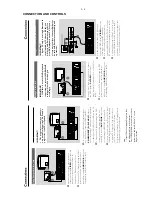
CONNECTION AND CONTROLS
IMPOR
T
ANT!
–
The type plate is located at the bottom
of the system.
–
Bef
or
e connecting the
A
C
po
w
er cord to
the wall outlet,
ensur
e that all
other connections ha
v
e
been made
.
–N
ev
er mak
e or chang
e an
y connections
with the po
w
er s
witched on.
Step 1:
Placing the speak
ers
and subw
oofer
Fr
ont
speak
er
( left )
Fr
ont
speak
er
( right )
VIEWING AREA
Subw
oof
er
1
Place the front left and r
ight speak
er
s at equal
distances from the
TV set and at an angle of
appro
ximatel
y 45 degrees from the listening
position.
2
Place the subw
oofer on the floor near the
TV
.
Notes:
–T
o avoid magnetic interf
er
ence
, do not position
the fr
ont speak
er
s too c
lose to your
TV set.
–
Allo
w adequate ventilation ar
ound the D
V
D
System.
Speak
er
(right)
Speak
er
(left)
FM
antenna
Subw
oof
er
AC
P
o
w
e
r
Step 3:
Connecting the contr
ol
cable
●
Connect the serial por
t mar
ked
“CONTR
OL
C
ABLE”
at the rear of the D
VD pla
yer to the
same por
t at the rear of the po
w
er amplif
ier
with the supplied flat control cab
le
.
Step 4:
Connecting
TV
IMPOR
T
ANT!
–Y
ou onl
y need to mak
e one video
connection fr
om the follo
wing options,
depending on the ca
pabilities of y
our
TV
.
–
Connect the D
VD system dir
ectl
y to
the TV
.
–A
SCAR
T connection allo
ws y
ou to
use f
eatur
es both
Audio and
Video
features on the D
VD Pla
y
e
r.
Using SCAR
T jack
AUDIO
IN
S-VIDEO
IN
VIDEO IN
TV IN
AUDIO
IN
S-VIDEO
IN
VIDEO IN
TV IN
●
Use the SC
AR
T
cable (b
lack) to connect the
D
VD Pla
yer’
s
SCAR
T
jack
to the cor
responding
Scar
t input jacks on the
TV
(cable not supplied)
.
Note:
–
Ensur
e that the
“TV”
indication on SC
AR
T cable
is connected to the
TV set and
“D
VD”
indication on
SC
AR
T cable is connected to the D
VD Play
er
.
Step 2:
Connecting speak
ers
1
Connect the speak
er wires to the SPEAKERS
terminals,
r
ight speak
er to
FR
ONT (
4
Ω
) R
and
left speak
er to
FR
ONT (
4
Ω
) L
. Full
y inser
t the
connector
s on the cab
les into the terminals and
fasten the hooks to ensure f
ir
m
connection.
2
Connect the passiv
e subwoofer to the
SUBW
OOFER (
8
Ω
)
ter
minal with the
supplied subw
oof
er cab
le b
y matching the plug
types.
Notes:
–
Ensur
e that the speak
er cables ar
e corr
ectly
connected.
Impr
oper connections may damag
e the
system due to shor
t-circuit.
–F
or optimal sound perf
ormance
, use the
supplied speak
ers
.
–
Do not connect mor
e than one speak
er to any
one pair of +/- speak
er jac
ks
.
–
Do not connect speak
er
s with an impedance
lo
wer than the speak
er
s supplied.
Please r
ef
er to
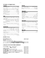
the SPECIFIC
ATIONS section of this manual.
Summary of Contents for MCD 728
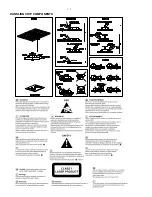
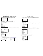
Page 2: ...1 1 HANDLING CHIP COMPONENTS ...
Page 3: ...1 2 ...
Page 5: ...2 2 ...
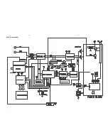
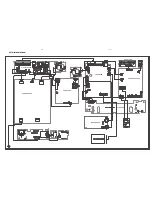
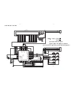
Page 14: ...5 2 5 2 SET BLOCK DIAGRAM ...
Page 17: ...6 2 6 2 LAYOUT DIAGRAM VFD BOARD ...
Page 19: ...7 2 7 2 LAYOUT DIAGRAM TUNER BOARD ...
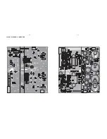
Page 21: ...8 2 8 2 LAYOUT DIAGRAM AMP BOARD ...
Page 23: ...9 2 9 2 LAYOUT DIAGRAM CPU BOARD ...