4 - 2
4 - 2
A
C
B1
B2
H
A.Remove Bottom Cover
A1.remove screws M2.5x4(8pcs)
B*.remove screws M3x10(6pcs) and T3x10(4pcs)
C*.remove screws T3x4(5pcs)
D.Remove Back Panel & Top Cover
D*remove screws T3x4(4pcs)and T3x6(1pcs)and T3x10(1pcs)
E. Remove Pre-AMP Board Assy
F. Remove AMP Board Assy
H.Remove AMP Front board assy
G.Remove SMPS board assy
I.Remove Side metal Plate
DISASSEMBLY DIAGRAM - AMP PART
D1
D1
D2
D3
F
F
I
E
G
G
Summary of Contents for MCD 728
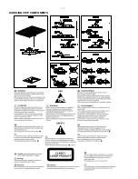
Page 2: ...1 1 HANDLING CHIP COMPONENTS ...
Page 3: ...1 2 ...
Page 5: ...2 2 ...
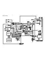
Page 14: ...5 2 5 2 SET BLOCK DIAGRAM ...
Page 17: ...6 2 6 2 LAYOUT DIAGRAM VFD BOARD ...
Page 19: ...7 2 7 2 LAYOUT DIAGRAM TUNER BOARD ...
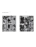
Page 21: ...8 2 8 2 LAYOUT DIAGRAM AMP BOARD ...
Page 23: ...9 2 9 2 LAYOUT DIAGRAM CPU BOARD ...


