Direction of Use
7-5
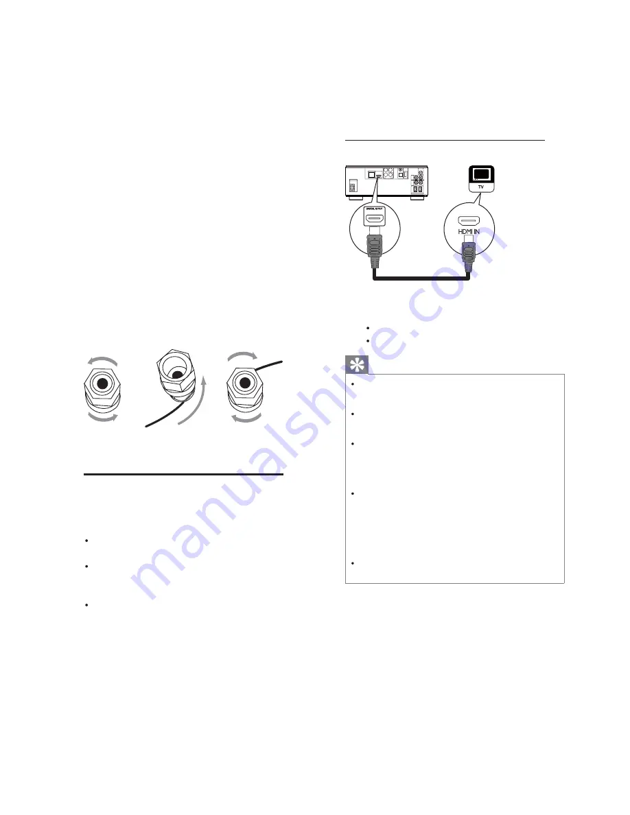
Option 1: Connect to the HDMI jack
COAXIAL
Pr/Cr
Pb/Cb
COMPONENT
W i - F i
Y
OPTICAL
DIGITAL AUDIO OUT
O
E
D
I
V
T
U
O
DIGITAL AV OUT
L AN
AC ~
AUX
IN
LINE
OUT
L
R
L
R
ANTENNA
FM
S P E A K E R O U T
R
L
HDMI IN
HDMI
1
Connect an HDMI cable (not supplied)
to:
the HDMI jack on this product.
the HDMI input jack on the TV.
Tip
If the TV has a DVI connector only, connect via
an HDMI/DVI adaptor. Connect an audio cable
for sound output.
You can optimize the video output. Press the
HDMI button repeatedly to select the best
resolution the TV can support.
If this product connects to a TV compatible
with 1080p or 1080p/24Hz, Philips
recommends HDMI category 2 cable, also
known as High Speed HDMI cable, for optimal
video and audio output.
To play the digital video images of a BD-video
or DVD-video via an HDMI connection, it
is necessary that both this product and the
display device(or an AV receiver/amplifier)
support a copyright protection system called
HDCP (high-bandwidth digital content
protection system).
This type of connection provides best picture
quality.
For the speaker side:
1
Unscrew the speaker connectors.
2
For the left speaker, identify the speaker
cable that is connected to the left
connectors on the main unit.
3
Insert fully the red end of the speaker
cable into the red (+) connector.
4
Screw the red (+) connector to secure
the cable.
5
Insert fully the silver end of the speaker
cable into the black (-) connector.
6
Screw the black (-) connector to secure
the cable.
7
Repeat steps 2-6 for the right speaker.
Connect video/audio cables
Select the best video connection that the TV
can support.
Option 1: Connect to the HDMI jack (for
an HDMI, DVI or HDCP-compliant TV).
Option 2: Connect to the component
video jacks (for a standard TV or
Progressive Scan TV).
Option 3: Connect to the composite
video jack (for a standard TV).
c
a
b
Summary of Contents for MBD3000/12
Page 23: ...8 2 Fig D3 A05 A04 A03 Fig D6 Fig D4 Cabinet Disassembly Instructions Fig D5 Fig D7 Fig D8 ...
Page 24: ...8 3 Cabinet Disassembly Instructions Fig D9 A06 A06 ...
Page 32: ...AMP and MCU Board Layout Diagram 13 3 13 3 ...
Page 34: ...VFD Display Board Layout Diagram 13 5 13 5 ...
Page 47: ...Decoder Board layout Diagram 13 18 13 18 ...
Page 49: ...Power Board Layout Diagram 13 20 13 20 ...
Page 51: ...Revision List Revision List Version 1 0 Initial Release 15 1 ...


