background image

1.5

Connect the supplied 360 cm (12 ft) data cable with two RJ-11
connectors between the junction box and the interface unit.
The orientation is not important -- either end may be
connected to either device.

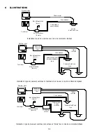
The next step is to connect the biphase control code output of
the interface unit to the data cable.  Typically, a single camera
site receiver/driver is connected, but the biphase output of the
interface unit is rated to handle up to 8 receiver/drivers when
connected in a "daisy chain" configuration to a maximum of
1.5 km (5000 ft).  For a "daisy chain" connection, the cable is
"looped" through each AutoDome camera or receiver/driver
along the way.  The last (and only the last) unit in the "daisy
chain" connection should be terminated.  All other
receiver/drivers should have their terminating resistor removed
when the 'looping' cable is connected.

If necessary, it is possible to 'expand' the single biphase output
of the interface unit using a LTC 8780 Series accessory unit.
The LTC 8780 Series unit provides up to 15 individual biphase
outputs, each rated to handle up to 8 receiver/drivers when
connected in a daisy chain configuration to a maximum of
1.5 km (5000 ft).  Follow the instructions supplied with the
LTC 8780 Series unit to configure it as a biphase distribution
unit.

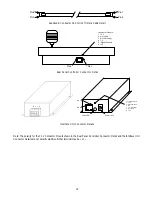
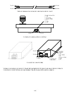
Connect shielded-twisted-pair cable (Belden 8760 or equivalent)
between the camera site receiver/driver location and the biphase
output connections located on the interface unit.  The
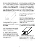
removable terminal block has four connections: "+", "-", and
two "S" (Shields) as shown in the diagram below.

Interface Unit Supplied with  LTC 5136

Select and maintain a wire color convention to avoid confusion
at the camera site(s).

Example: White to "+", Black to "-", and Shield to "S".

Note that either one of the 2 shield terminals of the interface
unit can be connected to the shield wire of the cable. 

4.5

AutoDome Camera or Receiver/Driver Site 
Configuration

Follow the standard installation instructions as provided with
the AutoDome Camera or Allegiant series Receiver/Driver unit
to connect the data cable to the unit. Set the Thumbwheel
located in the AutoDome camera or receiver/driver to the
camera number that will be selected on the Controller keypad.
Any desired camera number from 1 and 9999 can be used.

Video signals from the camera site are NOT connected to the
Controller.  The video signal(s) from the camera site(s) should
be connected to an appropriate viewing monitor or other video
processing equipment (switcher, multiplexer, etc.). 

5

CONTROLLER OPERATION

Operation is quite simple.  If the camera number to be
controlled is not visible in the LED displays, use the numeric
keypad to select the desired camera, then press the ENTER
button.  The camera can now be operated using the appropriate
joystick and/or lens controls.  If appropriate, prepositions scenes
and auxiliary functions can also be entered as desired.

Note that a delay lasting greater than 3-4 seconds while entering
a selection will result in the Controller returning to the default
camera entry mode.  If this condition occurs, simply begin the
selection again from the beginning.

A complete description of the controls and indicators is
provided in the section below.

5.1

Controls/Indicators

LED Indicators

: The four digit, 7-segment LED display is used

to display data entry and the selected camera number.

SET key

: This key is used to set preposition scenes of all

AutoDome cameras and Allegiant series receiver/drivers which
are equipped with this option.  Operate the joystick and lens
controls to position the camera to the desired scene to be
programmed.  Press the SET button, then enter the desired
preposition number on the numeric keypad (1 to 99).  Press
ENTER to store the position.

Certain preposition numbers are also used to program certain
AutoDome features.  Refer to the AutoDome operation manual
for a complete listing of the available features.

USER key

: This key is used to enter the Controller diagnostic

mode.  This test can be used to ensure that all Controller LEDs
and buttons are in working order.  This function will also
automatically calibrate the center position of the analog joystick.
Upon entering this mode, the Controller will sound a short
beep.  The display readouts and LEDs behind the first two rows
of buttons will also light for about two seconds.  During this
time the joystick will undergo calibration, so be careful not to
move it until the LEDs displays have gone dark.  Also, the
operator should note if there are any LED display failures
during the time that they are lit.

Summary of Contents for LTC 5136 Series

Page 1: ...LTC 5136 Series AutoDome Controllers Philips Communication Security Systems Eng F D E NL I Buy Bosch Burle Philips Cameras Parts TLS Electronics ...

Page 2: ...objects of any kind into this unit through openings as they may touch dangerous voltage points or short out parts that could result in a fire or electric shock Never spill liquid of any kind on the unit 16 Servicing Do not attempt to service this unit yourself as opening or removing covers may expose you to dangerous voltage or other hazards Refer all servicing to qualified service personnel 17 Da...

Page 3: ...perational Note The circuitry inside this unit contains a microprocessor and other electrostatic sensitive devices In the unlikely event that the unit stops responding due to an exposure to a static charge a user reset may be required The unit can be reset by unplugging it from the power supply waiting a few seconds and then restoring power CONTENTS 1 UNPACKING 1 1 2 SERVICE 1 2 3 DESCRIPTION 1 2 ...

Page 4: ...cted directly to RS 232 series AutoDome cameras or RS 232 Allegiant receiver driver units the installation is done without using the supplied interface unit For RS 232 applications a LTC 8557 Series Remote Keyboard Hookup kit should be purchased to simplify the installation process One of the junction boxes supplied with LTC 8557 Series kit can then be used to connect the RS 232 wires Tx and Gnd f...

Page 5: ... location close enough to the Controller unit so the supplied 360 cm 12 ft data cable can be used If desired four holes are provided for mounting the LTC 8557 Series junction box to a flat surface The power supply to power the Controller should also be located in a convenient location near the LTC 8557 Series junction box Connect the bayonet style connector of the power supply cable into the jack ...

Page 6: ...f cable not supplied suitable for use with RS 232 signals between the LTC 8557 Series junction box and the RS 232 transmission device If the distance between the box and device is much over 20 30 meters 60 90 ft the use of short haul modems supplied by others or other RS 232 line extender devices may be required They must be able to support an RS 232 simplex transmission rate of 9600 baud The LTC ...

Page 7: ...ill be selected on the Controller keypad Any desired camera number from 1 and 9999 can be used Video signals from the camera site are NOT connected to the Controller The video signal s from the camera site s should be connected to an appropriate viewing monitor or other video processing equipment switcher multiplexer etc 5 CONTROLLER OPERATION Operation is quite simple If the camera number to be c...

Page 8: ... keypad Press ENTER to complete the action Certain auxiliary numbers are also used to program certain AutoDome features Refer to the AutoDome operation manual for a complete listing of the available features OFF key This key is used to de activate auxiliary functions of the AutoDome cameras and Allegiant series receiver drivers Press the OFF button then enter the desired auxiliary number on the nu...

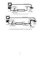
Page 9: ...erface Box Supplied Power Supply Unit Supplied Video Monitor Video Coax Cable Controller Biphase Code Typical AutoDome Cameras Sites Shielded Twisted Pair Cable Daisy Chain Configuration Interface Box Supplied Power Supply Unit Supplied Video Monitor Video Coax Cables Controller Video Switcher Biphase Code Typical AutoDome Cameras Sites Shielded Twisted Pair Cables Interface Box Supplied Power Sup...

Page 10: ...8557 Video Monitor Video Coax Cable Controller RS 232 Type Cable or Communication Link RS 232 Code RS 232 Code Typical AutoDome Camera Shielded Twisted Pair Cable LTC 8557 Junction Box Not Supplied Power Supply Unit Supplied with LTC 8557 Video Monitor Video Coax Cable Controller Power Supply Unit Supplied Interface Box Supplied RS 232 Type Cable or Communication Link Biphase Code RS 232 Code RS 2...

Page 11: ...s shown in the Rear Panel Controller Connector Detail and the Interface Unit Connector Details are not polarity sensitive Either terminal may be or 1 9 Pin 1 Pin 6 Pin 6 Pin 1 Pin 1 Pin 6 Connector Pinouts 1 12 V 2 Not used 3 Rx Not used 4 Tx 5 Signal Ground 6 12V Connector Pinouts 1 12 V 2 Signal Ground 3 Rx 4 Tx Not used 5 Not used 6 12V Pin 6 Pin 1 Code LED Power Jack ...

Page 12: ...1 10 ...

Page 13: ...ue opératoire L ensemble des circuits à l intérieur de cette unité contient un microprocesseur et d autres dispositifs sensibles à l électricité statique Dans le cas peu probable où l unité cesserait de fonctionner en raison de son exposition à une charge statique une réinitialisation peut être nécessaire L unité peut être réglée à nouveau en le débranchant de la source d alimentation Attendez que...

Page 14: ...l unité d interface se met à clignoter Le contrôleur n intègrant aucun connecteur vidéo les caméras doivent être connectées à un moniteur ou tout autre matériel approprié système de commutation multiplexeur etc afin que les signaux vidéo qu elles émettent soient retransmis Il ne faut pas utiliser l unité d interface fournie avec le contrôleur lors de l installation de ce dernier si l application d...

Page 15: ... données RS 232 générées par le contrôleur sont directement transmises aux caméras AutoDome ou aux modules de réception pilotage Allegiant dotés d un standard d interface RS 232 L unité d interface fournie avec le contrôleur n est pas utilisée dans cette application La caméra AutoDome ou le module de réception pilotage doivent être configurés via leurs microinterrupteurs internes pour fonctionner ...

Page 16: ...sur l une des faces latérales de la boîte de dérivation L unité d interface n étant pas polarisée il n est pas nécessaire de se préoccuper de la polarité lors de la connexion du câble d alimentation au bloc d alimentation Reliez le bloc d alimentation à une prise secteur appropriée Reliez les deux connecteurs RJ 11 du câble de transmission de données de 360 cm au contrôleur et à la boîte de dériva...

Page 17: ...e vous permet de le configurer en tant qu unité de distribution biphasée Connectez l une des extrémités du câble blindé à paire torsadée Belden 8760 ou équivalent au module de réception pilotage de la caméra de vidéo surveillance et l autre extrémité à la sortie biphasée de l unité d interface Le bloc de raccordement amovible est doté de quatre connecteurs et deux S câble blindé tel que sur le dia...

Page 18: ...21 Zoom CW 1x41 Zoom CCW 0x42 Veuillez noter que le chiffre x apparaissant dans les valeurs up haut down bas left gauche right droite et zoom fait référence à la vitesse et peut donc être modifiée en fonction de la distance d activation de la commande Camera Cette touche permet uniquement de corriger une erreur lors de la sélection du numéro d une caméra Il vous suffit pour cela d appuyez dessus p...

Page 19: ...ois Ceci vous permet d effacer des valeurs incorrectes sans quitter le mode courant Par contre si aucune donnée n apparaît sur l affichage LED le fait d appuyer une seule fois sur cette touche efface la configuration du contrôleur pour la remplacer par les valeurs par défaut FOCUS et IRIS mise au point et iris Ces interrupteurs à bascule permettent de contrôler les fonctions de mise au point et de...

Page 20: ... Video Switcher Biphase Code Typical AutoDome Cameras Sites Shielded Twisted Pair Cables Interface Box Supplied Power Supply Unit Supplied Video Monitor Video Coax Cables Controller Video Switcher TC8780 Optional Biphase Code Moniteur vidéo Bloc d alimentation fourni Contrôleur Unité d interface fournie Câble coaxial Code biphasé Câble blindé à paire torsadée Caméra AutoDome type Moniteur vidéo Co...

Page 21: ... Power Supply Unit Supplied Interface Box Supplied RS 232 Type Cable or Communication Link Biphase Code RS 232 Code RS 232 Code LTC 8557 Junction Box Not Supplied Moniteur vidéo Câbles coaxiaux Bloc d alimentation fourni avec le LTC 8557 Contrôleur Boîte de dérivation LTC 8557 non fournie Code RS 232 Caméra AutoDome type RS 232 Câble ou liaison de transmission RS 232 Code RS 232 Moniteur vidéo Câb...

Page 22: ...ne pouvant être positive ou négative Pin 1 Pin 6 Pin 6 Pin 1 Pin 1 Pin 6 Connector Pinouts 1 12 V 2 Not used 3 Rx Not used 4 Tx 5 Signal Ground 6 12V Connector Pinouts 1 12 V 2 Signal Ground 3 Rx 4 Tx Not used 5 Not used 6 12V Pin 6 Pin 1 Code LED Power Jack Broche 6 Broche 1 Broche 1 Broche 6 Broche 6 Broche 1 Broches du connecteur 1 12 V 2 Non utilisée 3 Rx non utilisée 4 Tx 5 Terre 6 12 V Broch...

Page 23: ...ektrostatischer Entladung Hinweis zum Betrieb Die Schaltung dieser Einheit umfaßt einen Mikroprozessor und andere elektrostatisch gefährdete Bauteile Spricht das Gerät aufgrund statischer Aufladung nicht mehr an so müssen Sie es unter Umständen zurücksetzen Ziehen Sie hierzu den Stecker warten Sie ein paar Sekunden und schließen Sie das Gerät dann erneut an INHALT 1 AUSPACKEN 3 1 2 WARTUNG 3 2 3 B...

Page 24: ...inen Zweiphasensteuercode umgewandelt wurde Am Controller befinden sich keine Videoanschlüsse Videokabel vom Kamerastandort sind an einem geeigneten Überwachungsmonitor oder sonstigen Videoverarbeitungsgeräten Umschalter Multiplexer usw anzuschließen Sofern die Einheit eine RS 232 Datenübertragungsverbindung benutzt oder direkt an RS 232 AutoDome Kameras oder RS 232 Allegiant Empfänger Treiber ang...

Page 25: ...tragung zum Kamerastandort Bei dieser Anwendungsform wird das vom Controller erzeugte RS 232 Datensignal direkt zu den RS 232 AutoDome Kameras oder RS 232 Allegiant Empfänger Treibern übertragen Die mitgelieferte Schnittstelleneinheit wird in dieser Konfiguration nicht benötigt Die AutoDome Kamera bzw der Empfänger Treiber muß über den internen DIP Schalter für den Betrieb mit 9600 Baud eingericht...

Page 26: ...tecker des Stromkabels mit dem Bajonettverschluß an der entsprechenden Buchse seitlich an der Anschlußdose an Beim Anschließen des Stromkabels am Netzteil spielt die Polarität keine Rolle da dies für den Betrieb der Schnittstelleneinheit unerheblich ist Schließen Sie das Netzteil an einer geeigneten Stromquelle an Schließen Sie das beiliegende Datenkabel 3 6m mit den beiden RJ 11 Steckern am Contr...

Page 27: ...s zu 8 Empfänger Treiber steuern kann Hinweise zur Konfigurierung der LTC 8780 Zusatzeinheit als Zweiphasenverteiler finden Sie in der beiliegenden Anleitung Verbinden Sie den Empfänger Treiber am Kamerastandort und die Zweiphasenausgänge an der Schnittstelleneinheit über ein STP Kabel Belden 8760 oder entsprechend An der Klemmleiste befinden sich vier Anschlüsse sowie zweimal S Schirmung wie unte...

Page 28: ...n Werten für Up Oben Down Unten Left Links Right Rechts und Zoom eine Geschwindigkeitsvariable darstellt die sich danach richtet über welche Distanz die Steuerung aktiviert wurde Camera Taste Diese Taste wird nur benutzt um einen Fehler bei der Auswahl einer Kameranummer zu korrigieren Falls während der Kameraauswahl versehentlich eine andere Taste gedrückt wurde kann der Controller über diese Tas...

Page 29: ...rsetzt Dadurch lassen sich falsch eingegebene Daten löschen ohne daß man den aktuellen Modus verlassen muß Falls die LED Anzeige keine Daten enthält wird mit dem ersten Betätigen der gesamte Controller in den Standardstatus versetzt FOCUS und IRIS Taste Diese Wippschalter dienen zur Steuerung der Fokus und Blendenfunktionen Joystick Indem man den Joystick nach links oder rechts bewegt wird die jew...

Page 30: ... Video Switcher Biphase Code Typical AutoDome Cameras Sites Shielded Twisted Pair Cables Interface Box Supplied Power Supply Unit Supplied Video Monitor Video Coax Cables Controller Video Switcher TC8780 Optional Biphase Code Videomonitor Stromversorgungseinheit im Lieferumfang Controller Schnittstelleneinheit im Lieferumfang Koaxialkabel Zweiphasencode STP Kabel AutoDome Standardkamera Videomonit...

Page 31: ...Unit Supplied Interface Box Supplied RS 232 Type Cable or Communication Link Biphase Code RS 232 Code RS 232 Code LTC 8557 Junction Box Not Supplied Videomonitor Koaxialkabel Stromversorgungsein heit im Lieferumfang von LTC 8557 Controller LTC 8557 Anschlußdose nicht im Lieferumfang RS 232 Code AutoDome Kamera RS 232 Modell RS 232 Kabel oder Kommunikationsverbindung RS 232 Code Videomonitor Koaxia...

Page 32: ...neinheit erfordern keine bestimmte Polarität Jeder Pol kann oder sein Pin 1 Pin 6 Pin 6 Pin 1 Pin 1 Pin 6 Connector Pinouts 1 12 V 2 Not used 3 Rx Not used 4 Tx 5 Signal Ground 6 12V Connector Pinouts 1 12 V 2 Signal Ground 3 Rx 4 Tx Not used 5 Not used 6 12V Pin 6 Pin 1 Code LED Power Jack Stift 6 Stift 1 Stift 1 Stift 6 Stift 6 Stift 1 Anschlußstifte 1 12 V 2 Frei 3 Rx Empfangen Frei 4 Tx Senden...

Page 33: ...cas NOTA Para manipular placas de circuito impreso sensibles a la corriente electrostática debe llevar una muñequera con toma de tierra y debe observar las medidas de seguridad ESD adecuadas Nota operacional El circuito que incorpora esta unidad contiene un microprocesador y otros dispositivos sensibles a la corriente estática En el caso poco probable de que la unidad deje de responder debido a un...

Page 34: ...ciona una vía para conectar la alimentación a la unidad de controlador Un LED situado en la unidad de interfaz se enciende intermitentemente para indicar que los datos RS 232 procedentes del controlador se han convertido correctamente en código de control bifásico No hay conexiones de vídeo con el controlador Las señales de vídeo procedentes de los emplazamientos de las cámaras deben conectarse a ...

Page 35: ...mplazamiento de la cámara En esta aplicación los datos RS 232 generados por el controlador se conectan directamente a cámaras AutoDome serie RS 232 o a unidades de motor receptor Allegiant RS 232 En esta aplicación no se utiliza la unidad de interfaz suministrada La cámara AutoDome o el motor receptor se debe ajustar a través de su conmutador DIP interno para funcionar a 9 600 baudios Instale una ...

Page 36: ...ebe conectar el cable de la fuente de alimentación a la fuente de alimentación la polaridad no tendrá importancia ya que la unidad de interfaz no es sensible a la polaridad Conecte la fuente de alimentación a una toma de corriente Conecte el cable de datos de 360 cm suministrado provisto de dos conectores RJ 11 entre la unidad de controlador y la caja de conexión La orientación carece de importanc...

Page 37: ... Siga las instrucciones suministradas con la unidad Serie LTC 8780 para configurarla como una unidad de distribución bifásica Conecte el cable de par trenzado armado Belden 8760 o equivalente entre la posición del motor receptor en el emplazamiento de la cámara y las conexiones de salida bifásica situadas en la unidad de interfaz El bloque de terminales desmontable dispone de cuatro conexiones y d...

Page 38: ...1 6 0028 Izquierda 1x52 7 0013 Derecha 0x55 8 0021 Zoom CW 1x41 Zoom CCW 0x42 Obsérvese que la cifra x mostrada para los valores de arriba abajo izquierda derecha y zoom indica un valor de velocidad y cambiará dependiendo de lo mucho que se active el mando Tecla Camera esta tecla sólo se utiliza para corregir un error cuando se selecciona un número de cámara Si se pulsa accidentalmente otra tecla ...

Page 39: ...tos sin salir del modo seleccionado en ese momento Si no aparecen datos en la pantalla de indicadores LED la primera pulsación borrará todo el contenido del controlador que revertirá al estado predeterminado Teclas FOCUS e IRIS estos conmutadores basculantes se utilizan para controlar las funciones de enfoque e iris de la lente Palanca de mandos cuando se mueve la palanca de mandos a la izquierda ...

Page 40: ...Typical AutoDome Cameras Sites Shielded Twisted Pair Cables Interface Box Supplied Power Supply Unit Supplied Video Monitor Video Coax Cables Controller Video Switcher TC8780 Optional Biphase Code Monitor de vídeo Unidad de fuente de alimentación suministrada Controlador Caja de interfaz suministrada Cable coaxial de vídeo Código bifásico Cable de par trenzado armado Cámara AutoDome típica Monitor...

Page 41: ...face Box Supplied RS 232 Type Cable or Communication Link Biphase Code RS 232 Code RS 232 Code LTC 8557 Junction Box Not Supplied Monitor de vídeo Cable coaxial de vídeo Unidad de fuente de alimentación suministrada con LTC 8557 Controlador Caja de conexión LTC 8557 no suministrada Código RS 232 Cámara AutoDome típica modelo RS 232 Cable de tipo RS 232 o enlace de comunicaciones Código RS 232 Moni...

Page 42: ...polaridad Cualquiera de los terminales puede ser o Pin 1 Pin 6 Pin 6 Pin 1 Pin 1 Pin 6 Connector Pinouts 1 12 V 2 Not used 3 Rx Not used 4 Tx 5 Signal Ground 6 12V Connector Pinouts 1 12 V 2 Signal Ground 3 Rx 4 Tx Not used 5 Not used 6 12V Pin 6 Pin 1 Code LED Power Jack Patilla 6 Patilla 1 Patilla 1 Patilla 6 Patilla 6 Patilla 1 Conexionado del conector 1 12 V 2 No se utiliza 3 Rx no se utiliza ...

Page 43: ...or elektrostatische ontlading Opmerking voor gebruiker Deze eenheid bevat een microprocessor en andere schakelingen die gevoelig zijn voor elektrostatische ontlading Mocht het apparaat ooit door een statische ontlading niet meer werken voer dan een reset uit Daarvoor ontkoppelt u het systeem van de voeding wacht enkele seconden en sluit dan de voedingsspanning weer aan INHOUD 1 UITPAKKEN 5 1 2 SER...

Page 44: ...en systeem gebruik maakt van een RS232 dataverbinding van rechtstreekse aansluitingen op AutoDome camera s met een RS232 poort of van Allegiant receiver drivers met een RS232 poort dan wordt de bijgeleverde interface eenheid niet gebruikt Voor RS232 toepassingen moet een LTC 8557 interface kit worden aangeschaft die het installeren vereenvoudigt Met een van de aansluiteenheden bij die kit kunnen d...

Page 45: ...k aan te schaffen LTC 8557 kits op minder dan 360 cm van de controller zodat de bijgeleverde datakabel kan worden gebruikt Deze kits bevatten vier gaatjes waarmee zij op een egaal oppervlak kunnen worden gemonteerd Ook de voedingseenheid voor de voedingsspanning naar de controller moet op een makkelijk bereikbare plaats in de buurt van de kit LTC 8557 worden gemonteerd Sluit de bajonet connector v...

Page 46: ...nodig zijn Die moet geschikt zijn voor simplex dataverkeer met 9600 baud De LTC 8557 aansluiteenheid heeft een afneembaar klemmenblokje met vier aansluitingen voor dataverbindingen die genummerd zijn als 1 2 3 en 4 zoals hieronder afgebeeld Bij LTC 8557 kit geleverde aansluiteenheid De pennen 1 en 2 worden niet gebruikt Pen 3 is de Tx RS232 uitgang van de controller en pen 4 is de signaalaarde Geb...

Page 47: ...oudig Als de LED s geen cameranummer tonen geef dan met de cijfertoetsen het nummer op van de camera die u wilt besturen en druk dan op de ENTER toets Daarna kunt u de gekozen camera bedienen met de joystick en of lensbesturing Indien gewenst kunt u ook voorkeuzeposities op te nemen gebieden en extra functies opgeven Als u het invoeren van een opdracht meer dan 3 tot 4 seconden onderbreekt dan gaa...

Page 48: ...chakelt u extra functies van AutoDome camera s en Allegiant receiver drivers uit Druk op de OFF toets en geef met de cijfertoetsen het nummer van de gewenste functie op Druk op ENTER om uw keuze te bevestigen Bepaalde nummers voor extra functies worden ook gebruikt voor het programmeren van AutoDome functies De AutoDome handleiding geeft een overzicht van alle beschikbare functies Cijfertoetsen Me...

Page 49: ...cher Biphase Code Typical AutoDome Cameras Sites Shielded Twisted Pair Cables Interface Box Supplied Power Supply Unit Supplied Video Monitor Video Coax Cables Controller Video Switcher TC8780 Optional Biphase Code Monitor Voedingseenheid bijgeleverd Controller Interface eenheid bijgeleverd Coaxiale videokabel Biphase code Afgeschermde getwiste kabel Gangbare AutoDome camera Monitor Controller Voe...

Page 50: ... Unit Supplied Interface Box Supplied RS 232 Type Cable or Communication Link Biphase Code RS 232 Code RS 232 Code LTC 8557 Junction Box Not Supplied Monitor Coaxiale videokabel Voedingseenheid geleverd bij LTC 8557 Controller LTC 8557 aansluiteenheid niet bijgeleverd RS232 code Gangbare AutoDome camera RS232 model RS232 kabel of dataverbinding RS232 code Monitor Coaxiale videokabel Voedingseenhei...

Page 51: ...iting is geschikt voor of Pin 1 Pin 6 Pin 6 Pin 1 Pin 1 Pin 6 Connector Pinouts 1 12 V 2 Not used 3 Rx Not used 4 Tx 5 Signal Ground 6 12V Connector Pinouts 1 12 V 2 Signal Ground 3 Rx 4 Tx Not used 5 Not used 6 12V Pin 6 Pin 1 Code LED Power Jack Pen 6 Pen 1 Pen 1 Pen 6 Pen 6 Pen 1 Penfuncties 1 12 V 2 Niet gebruikt 3 Rx Niet gebruikt 4 Tx 5 Signaalaarde 6 12 V Pen 1 Pen 6 Code LED Jack connector...

Page 52: ...5 10 ...

Page 53: ...la sicurezza ESD Nota operativa Il circuito all interno di questa unità contiene un microprocessore ed altri dispositivi sensibili alle scariche elettrostatiche Nell eventualità in cui l unità si guasti a causa di una scarica elettrica potrebbe essere necessaria un operazione di ripristino da parte dell utente In questo caso scollegare l unità dall alimentatore attendere pochi secondi quindi riatt...

Page 54: ... utilizza una connessione dati RS 232 o è collegata direttamente a telecamere AutoDome della serie RS 232 o ad unità receiver driver Allegiant della serie RS 232 non è necessario installare anche l unità interfaccia in dotazione Per semplificare l installazione nelle applicazioni RS 232 è necessario acquistare un kit Collegamento tastiera remota Serie LTC 8557 Una delle scatole di raccordo in dota...

Page 55: ...a 9600 baud Installare una delle scatole di raccordo in dotazione con i kit Serie LTC 8557 da acquistare separatamente abbastanza vicino all unità Controller da poter utilizzare il cavo dati da 360 cm 12 ft in dotazione Sulla scatola di raccordo Serie LTC 8557 sono disponibili quattro fori per un eventuale installazione su una superficie piana Anche l alimentatore per alimentare il Controller deve...

Page 56: ...1 tra l unità Controller e la scatola di raccordo L orientamento non è importante sia un estremità che l altra possono essere collegate ad entrambi i dispositivi Collegare un cavo sufficientemente lungo ed utilizzabile con segnali RS 232 non in dotazione tra la scatola di raccordo serie LTC 8557 ed il dispositivo di trasmissione RS 232 Se la distanza tra la scatola ed il dispositivo è superiore a ...

Page 57: ...ato in S Ricordare che entrambi i terminali schermati dell unità interfaccia possono esser collegati al cavetto schermato del cavo 4 5 Configurazione postazione telecamera AutoDome o Receiver Driver Seguire le istruzioni per l installazione standard fornite con la telecamera AutoDome o l unità receiver driver Serie Allegiant per collegare il cavo dati all unità Impostare la rotellina sulla telecam...

Page 58: ...e operativo AutoDome per un elenco completo delle funzioni disponibili Tasto ON ATTIVA Questo tasto attiva le funzioni ausiliari delle telecamere AutoDome e dei receiver driver della serie Allegiant Premere il tasto ON quindi digitare il numero ausiliare desiderato sul tastierino numerico Premere ENTER INVIO per terminare la procedura Con alcuni numeri di preposizonamento è inoltre possibile progr...

Page 59: ...de Typical AutoDome Cameras Sites Shielded Twisted Pair Cables Interface Box Supplied Power Supply Unit Supplied Video Monitor Video Coax Cables Controller Video Switcher TC8780 Optional Biphase Code Monitor Unità d alimentazione in dotazione Controller Scatola di interfaccia in dotazione Cavo video coassiale Codice bifase Doppino schermato Telecamera AutoDome tipica Monitor Controller Unità d ali...

Page 60: ...y Unit Supplied Interface Box Supplied RS 232 Type Cable or Communication Link Biphase Code RS 232 Code RS 232 Code LTC 8557 Junction Box Not Supplied Monitor Cavo video coassiale Unità d alimentazione in dotazione con LTC8557 Controller Scatola di raccordo LTC 8557 in dotazione Codice RS 232 Telecamera AutoDome tipica modello RS 232 Cavo RS 232 o percorso di comunicazione Codice RS 232 Monitor Ca...

Page 61: ...n è importante Entrambi i terminali possono essere o Pin 1 Pin 6 Pin 6 Pin 1 Pin 1 Pin 6 Connector Pinouts 1 12 V 2 Not used 3 Rx Not used 4 Tx 5 Signal Ground 6 12V Connector Pinouts 1 12 V 2 Signal Ground 3 Rx 4 Tx Not used 5 Not used 6 12V Pin 6 Pin 1 Code LED Power Jack Pin 6 Pin 1 Pin 1 Pin 6 Pin 6 Pin 1 Piedinatura del connettore 1 12V 2 Inutilizzato 3 Rx inutilizzato 4 Tx 5 Signal ground 6 ...

Page 62: ...6 10 ...

Page 63: ...9 23 1999 Philips Electronics N V Printed In U S A 1999 Philips Communications Security Systems Inc All Rights Reserved Philips is a registered trademark of Philips Electronics N V Data subject to change without notice ...

Reviews: