background image

4

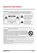
SICHERHEITSVORKEHRUNGEN

Aus Platzgründen kann diese Warnung auf der Unterseite des
Gerätes angebracht sein.

Das Blitzsymbol im gleichseitigen Dreieck soll den
Benutzer auf nicht isolierte “Hochspannung” im
Gehäuse aufmerksam machen, die eventuell stark
genug ist, um einen elektrischen Schlag zu
verursachen. 

Das Ausrufezeichen im gleichseitigen Dreieck soll den
Benutzer auf wichtige Bedienungs- und
Wartungsanleitungen in der dem Gerät beigefügten
Literatur aufmerksam machen.

Achtung! Die Installation sollte nur von qualifiziertem
Kundendienstpersonal gemäß jeweilig zutreffender
Elektrovorschriften ausgeführt werden.

PRECAUCIONES DE SEGURIDAD

Debido a limitaciones de espacio, esta etiqueta puede aparecer
en la parte inferior de la unidad.

El símbolo representado por un relámpago con punta
de flecha dentro de un triángulo equilátero, se
muestra con el objetivo de alertar al usuario que
existen “voltages peligrosos” sin aislamiento, dentro de
la cubierta de la unidad. Dichos voltages pueden ser
de tal magnitud que constituyen un riesgo de choque
eléctrico a personas.

El símbolo de exclamación dentro de un triángulo
equilátero, se muestra con el objetivo de alertar al
ususario de que instrucciones de operación y
mantenimiento importantes acompañan al equipo.

Atención: La instalación de este equipo debe ser
realizada por personal capacitado, solo en acuerdo, y
en cumplimiento de normas del "National Electric
Code" (Código Eléctrico Nacional) ó las normas del
Gobierno Nacional Local.

VORSICHT: UM EINEN ELEKTRISCHEN
SCHLAG ZU VERMEIDEN, ABDECKUNG NICHT
ENTFERNEN. WARTUNGEN ALLER ART
QUALIFIZIERTEM PERSONAL ÜBERLASSEN. 

WARNUNG
UM FEUER ODER ELEKTRISCHE SCHLÄGE
ZU VERMEIDEN, SETZEN SIE DAS GERÄT
NIEMALS REGEN ODER FEUCHTIGKEIT AUS.

PRECAUCION:  PARA REDUCIR EL RIESGO DE
CHOQUE ELÉCTRICO, FAVOR NO ABRIR LA
CUBIERTA. ESTE EQUIPO NO CONSTA DE
PIEZAS O PARTES QUE REQUIEREN SERVICIO
O MANTENIMIENTO. PARA REPARACIONES
FAVOR REFERIRSE A UN TÉCNICO
CALIFICADO. 

PELIGRO
PARA EVITAR EL PELIGRO DE INCENDIO Ó
CHOQUE ELÉCTRICO, NO EXPONGA A LA
LLUVIA Ó HUMEDAD.

Summary of Contents for LTC 2914/91

Page 1: ...LTC 2914 91 LTC 2917 91 LTC 2919 90 Color Video Monitors Installation Instructions Eng Philips Communication Security Imaging Photo inset shows LTC 2919 90 with rack mount kit installed sold separately ...

Page 2: ...y kind on the unit 16 Servicing Do not attempt to service this unit yourself as opening or removing covers may expose you to dangerous voltage or other hazards Refer all servicing to qualified service personnel 17 Damage Requiring Service Unplug the unit from the outlet and refer servicing to qualified service personnel under the following conditions a When the power supply cord or plug is damaged...

Page 3: ...l utilisateur de la présence d une tension dangereuse non isolée à l intérieur de l appareil et d une valeur suffisante pour constituer un risque d électrocution Le point d exclamation contenu dans un triangle équilatéral avertit l utilisateur de la présence dans la documentation qui accompagne l appareil de consignes d utilisation et de maintenance importantes Attention L installation doit être e...

Page 4: ... aislamiento dentro de la cubierta de la unidad Dichos voltages pueden ser de tal magnitud que constituyen un riesgo de choque eléctrico a personas El símbolo de exclamación dentro de un triángulo equilátero se muestra con el objetivo de alertar al ususario de que instrucciones de operación y mantenimiento importantes acompañan al equipo Atención La instalación de este equipo debe ser realizada po...

Page 5: ...ugh BNC connectors and one 1 Y C loop through input with two 2 4 pin mini DIN connectors located on the rear of the monitors The video input selection buttons A B Y C and SEQ are located on the front of the monitor For applications that require audio two 2 sets of audio phono jack connectors are provided on the rear panel 1 2 Unpacking Read these instructions carefully Unpack carefully Monitors ar...

Page 6: ...nnectors 10 Audio A B Connectors 13 Mains Input Socket 12 Y C S video Connectors 11 Video Impedance Y C Switch 7 Power Switch LED 5 Video Input Y C Selection Control 6 Sequence Display Selection Control OSD A B Y C SEQ Fig 1 Monitor Models LTC 2914 91 LTC 2917 91 and LTC 2919 90 Front and Rear Views Fig 2 Connecting a Single Monitor Video Camera A B HiZ 75 Ω HiZ 75 Ω A A Video B HiZ 75 Ω In Y C Vi...

Page 7: ...5 Ω Y C HiZ 75 Ω Fig 3b Connecting Multiple Monitors A A Video B HiZ 75 Ω In Y C Video Out Audio B A B HiZ 75 Ω Y C HiZ 75 Ω A A Video B HiZ 75 Ω In Y C Video Out Audio B A B HiZ 75 Ω Y C HiZ 75 Ω A A Video B HiZ 75 Ω In Y C Video Out Audio B A B HiZ 75 Ω Y C HiZ 75 Ω A B HiZ 75 Ω HiZ 75 Ω A B HiZ 75 Ω HiZ 75 Ω A B HiZ 75 Ω HiZ 75 Ω Video Camera ...

Page 8: ...ion mode the impedance must be set to 75 Ohm by sliding the impedance switch to the 75 Ω position In the multiple connector mode Fig 3a 3b the impedance switch is set to the HiZ position This allows the video signal to be passed on to another monitor or device CAUTION The last monitor or device in the chain which is receiving the video signal must be terminated i e the impedance switch set to the ...

Page 9: ... switch again to turn the monitor OFF 3 2 On screen Display OSD Menu Press the OSD push button Fig 1 Item 1 to obtain the following menu options Tint Adjusts color level for best results adjust until skin color is natural See the OSD Tint menu configuration below NOTE Applicable to NTSC only not available in PAL format Color Adjusts the overall color intensity of the screen display See the OSD Col...

Page 10: ...nts are made directly from the front panel using the cursor and adjustment control and button Fig 2 Item 2 4 SPECIFICATIONS 4 1 Electrical Display Tube LTC 2914 91 35 6 cm 14 in measured diagonally 90 deflection dot stripe pitch 0 22 mm LTC 2917 91 44 cm 17 in measured diagonally 90 deflection dot stripe pitch 0 28 mm LTC 2919 90 48 3 cm 19 in measured diagonally 90 deflection dot stripe pitch 0 2...

Page 11: ...ected 2 Video cable is disconnected Resolution 1 Select and push correct video input button 2 Check video cable for proper connection and correct accordingly Power On No Sound 1 Incorrect cable connection configuration 2 Audio cable is disconnected 3 Volume output is set too low Resolution 1 Ensure that cable connection configuration is correct see Section 2 5 2 Connect audio cable firmly 3 Adjust...

Page 12: ...0 2001 by Philips Electronics N V Printed in U S A 2001 by Philips Communication Security Imaging Inc All Rights Reserved Philips is a registered trademark of Philips Electronics N V Data subject to change without notice ...

Reviews: