


Mechanical Instructions
4.
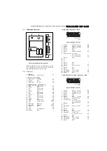
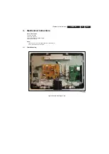
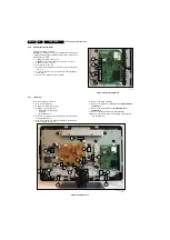
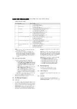
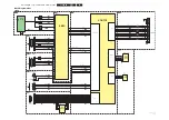
4.3.6
Small Signal Board (SSB)
Refer to next figure for details.
Caution:
it is mandatory to remount all different screws at their
original position during re-assembly. Failure to do so may result
in damaging the SSB.
1.
Unplug the LVDS connector [1].
Caution:
be careful, as this is a very fragile connector!
2.
Unplug the connectors [2].
3.
Remove the screws [3].
4.
The SSB can now be taken out of the set, together with the
side cover.
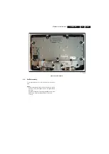
5.
To remove the side cover, push back the clamp [4] using a
screw driver.
6.
Pull the cover sidewards from the SSB.
Figure 4-8 Small Signal Board
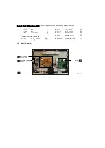
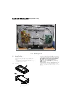
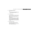
4.3.7
LCD Panel
Refer to next figures for details.
1.
Remove the stand [1].
2.
Unplug the LVDS connector [2].
3.
Unplug connectors [3] from
–
Main Power Supply Panel
–
Speakers
–
IR & LED Panel.
4.
Remove any adhesive tape [4] that prevents cables being
removed from the set.
5.
Remove all cables from clamps [5] that prevents them from
being removed from the set.
6.
Remove the VESA stand [6].
7.
Remove the Main Power Supply Panel
together with it’s
subframe
[7].
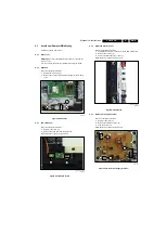
8.
Remove the Small Signal Board
together with it’s
subframe
[8].
9.
Remove the subframe that holds the stand [9].
10. Remove the clamps that secure the LCD Panel [10] and
take the panel out.
Figure 4-9 LCD Panel -1-
4
3
3
3
3
3
2
(
3
x
)
2
1
I_1
8
170_051.ep
s
3
1070
8
7
7
7
7
1
1
1
1
8
8
8
8
6
6
5
2
3
(
2x
)
3
3
3
4
3
4
4
4
3
I_1
8
170_052.ep
s
3
1070
8


