


Service Modes, Error Codes, and Fault Finding
5.
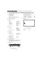
5.5
Error Codes
In case of non-intermittent faults, clear the error buffer before
you begin the repair. These to ensure that old error codes are
no longer present.
If possible, check the entire contents of the error buffer. In
some situations, an error code is only the result of another error
code and not the actual cause (e.g., a fault in the protection
detection circuitry can also lead to a protection).
Table 5-3 Error Code Table
5.6
The Blinking LED Procedure
Via this procedure, you can make the contents of the error
buffer visible via the front LED. This is especially useful when
there is no picture.
When the SDAM is entered, the LED will blink the contents of
the error-buffer.
•
n short blinks (n = 1 - 14),
•
When all the error-codes are displayed, the sequence
finishes with a LED blink of 3 s,
•
The sequence starts again.
Example
of error buffer: 12 9 6 0 0
After entering SDAM:
•
12 short blinks followed by a pause of 3 s,
•
9 short blinks followed by a pause of 3 s,
•
6 short blinks followed by a pause of 3 s,
•
1 long blink of 3 s to finish the sequence,
•
the sequence starts again.
5.7
Protections
If a fault situation is detected an error code will be generated
and if necessary the set will be put in the protection mode.
Blinking of the red LED at a frequency of 3 Hz indicates the
protection mode. In some error cases, the microprocessor
does not put the set in the protection mode. The error codes of
the error buffer can be read via the service menu (SDAM), the
blinking LED procedure or via ComPair.
To get a quick diagnosis the chassis has one service modes
implemented:
•
The Service Default Alignment Mode (SDAM). Start-up of
the set in a predefined way and adjustment of the set via a
menu and with the help of test patterns.
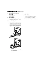
5.8
Repair Tips
Below some failure symptoms are given, followed by a repair
tip.
•
Set is dead and makes hiccupping sound.
“Main
Supply” is available. Hiccupping stops when de-soldering
L5563, meaning that problem is in the “Main Supply” line.
No output voltages at LOT, no horizontal deflection.
Reason: line transistor 7421 is defective.
•
Set is dead, and makes no sound.
Check power supply
IC 7520. Result: voltage at pins 2, 6, 7, 9 and 11 are about
180 V and pin 14 is 0 V. The reason why the voltage on
these pins is so high is because the output driver (pin 11)
has an open load. That is why MOSFET 7521 is not able to
switch. Reason: feedback resistor 3523 is defective.
Caution:
be careful measuring on the gate of 7521;
circuitry is very high ohmic and can easily be damaged!
•
Set is in hiccup mode and shuts down after 8 s.
Blinking
LED (set in SDM mode) indicates error 5. As it is unlikely
that the “POR” and “+8V protection” happen at the same
time, measure the “+8V”. If this voltage is missing, check
transistor 7491 and 7496.
•
Set is non-stop in hiccup mode.
Set is in over current
mode; check the secondary sensing (opto coupler 7515)
and the “Main Supply” voltage. Signal “Stdby_con” must be
logic low under normal operation conditions and goes to
high (3.3 V) under standby and fault conditions.
•
Set turns on, but without picture and sound.
The screen
shows snow, but OSD and other menus are okay. Blinking
LED procedure indicates error 11, so problem is expected
in the tuner (pos. 1000). Check presence of supply
voltages. As “5V” at pin 5 and 7 are okay,
“VT_supply” at pin 9 is missing. Conclusion: resistor 3449
and 3450 are defective
ERROR Device
Error description
Check item
Diagram
0
Not applicable
No Error
-
-
1
Not applicable
X-Ray Protection (USA)
7421, 2423, 6421, 6422
A2
2
Not applicable
Horizontal Protection
7421, 7422, 7423
A2
3
Not applicable
Vertical Protection
7461, 7462, 7463, 7464, 7465, 7466
A2
4
TDA9853H
Tone control & Audio processor I
2
C
identification error
7861 (Stereo/Sap)
A5
5
TDA93XX
POR 3.3V / 8V Protection
7200, 7541, 7491, 7493, 7496
A4, A1
6
I
2
C bus
General I
2
C bus error
7200, 3604, 3605
A4
7
Not applicable
-
-
-
8
Not applicable
E/W Protection (Large Screen)
-
-
9
M24C16
NVM I
2
C identification error
7641, 3641, 3642, 3643
A4
10
Tuner
Tuner I
2
C identification error
1000, 3003, 3004
A3
11
Not applicable
Black current loop protection
3313, 7307, 7308, 7309, 7310, 7311, 7312, 7313,
7314, 7315, 7316, 7317, 7318, CRT
B1
12
Not applicable
MAP I
2
C identification error (USA)
-
-
13
Not applicable
VC I
2
C identification error (Eu)
-
-
14
Not applicable
DVD I
2
C identification error
-
-
Summary of Contents for L03.2L AA
Page 1: ......