background image

Alignments

EN 45

L01.2A AB

8.

4.

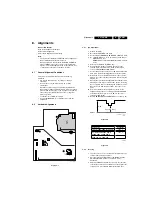
Select AGC with the UP/DOWN cursor keys.

5.

Adjust the AGC-value (default value is 28) with the LEFT/
RIGHT cursor keys until the voltage at pin 1 of the tuner lies 
between 3.8 and 2.3 V.

6.

Select AFW with the UP/DOWN cursor keys and set to 
OFF.

7.

Switch the set to STANDBY.

YD (Y-delay)

Always set to 8.

CL (cathode drive level)

Always set to 7.

AFA

Read only bit, for monitoring purpose only.

AFB

Read only bit, for monitoring purpose only.

8.3.3

White Tone

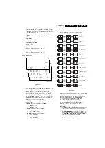
Figure 8-8 

 
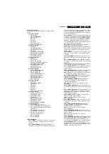
In the WHITE TONE sub menu, the values of the black cut off 
level can be adjusted. Normally, no alignment is needed for the 
WHITE TONE. You can use the given default values.
The colour temperature mode (NORMAL, COOL and WARM) 
and the colour (R, G, and B) can be selected with the UP/
DOWN RIGHT/LEFT cursor keys. The value can be changed 
with the LEFT/RIGHT cursor keys. First, select the values for 
the NORMAL colour temperature. Then select the values for 
the COOL and WARM mode. After alignment, switch the set to 
standby, in order to store the alignments.
 
Default settings:
1.

NORMAL

 (colour temperature = 11500 K):

NORMAL R = 32

NORMAL G = 35

NORMAL B = 30

2.

COOL

 (colour temperature = 14000 K):

DELTA COOL R = 0

DELTA COOL G = -5

DELTA COOL B = 5

3.

WARM

 (colour temperature = 8200 K):

DELTA WARM R = 8

DELTA  WARM  G  =  -3

DELTA WARM B = 2 

8.3.4

Geometry

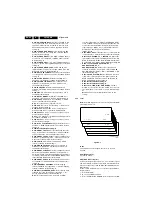
The geometry alignments menu contains several items to align 
the set, in order to obtain correct picture geometry.

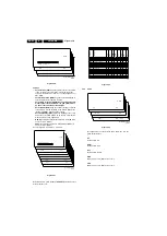
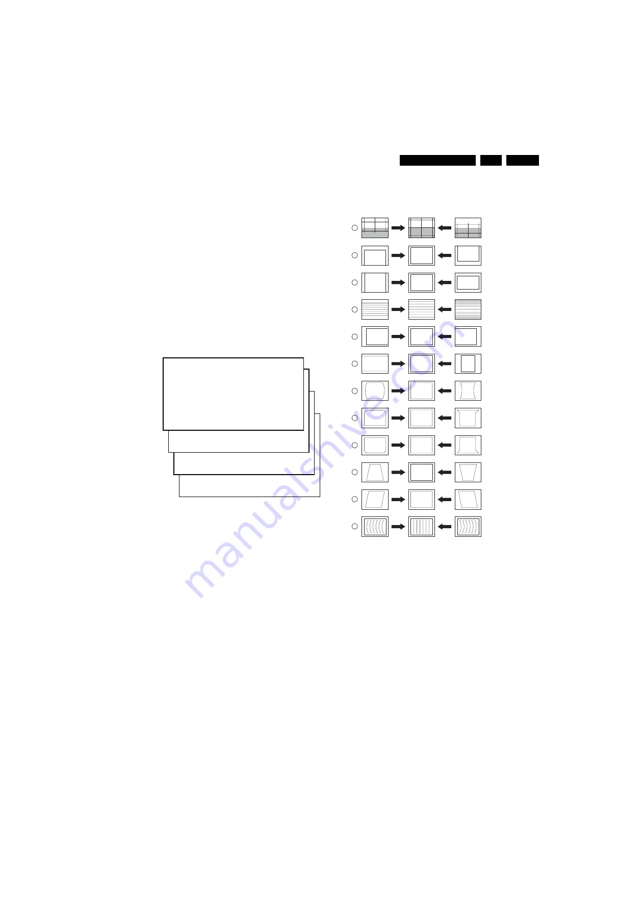
Figure 8-9 

Connect an external video pattern generator to the aerial input 
of the TV-set and  input a crosshatch test pattern. Set the 
generator amplitude to at least 1 mV and set frequency to 
475.25 MHz (PAL/SECAM) or 61.25 MHz (NTSC).
1.

Set 'Smart Picture' to NATURAL (or MOVIES).

2.

Activate the SAM menu (see chapter 5). 

3.

Go to the GEOMETRY sub menu.  

4.

Choose HORIZONTAL or VERTICAL alignment

Now you can perform  the following alignments:

Horizontal:

Horizontal Parallelogram (HP) 

Align straight vertical lines 

in the top and the bottom; vertical rotation around the 
centre.

Horizontal Bow (HB) 

Align straight horizontal lines in the 

top and the bottom; horizontal rotation around the centre.

Horizontal Shift (HSH) 

Align the horizontal centre of the 

picture to the horizontal centre of the CRT.

See also Figure 8-9 numbers 11, 12 and 5.

S A M

N O R M A L

>

(1)

C O O L  


>

(2)

W A R M

>

(3)

(1)

N O R M A L

R E D

X X

N O R M A L

G R E E N

X X

N O R M A L

B L U E

X X

(2)

D

C O O L

R E D

X X

D

C O O L

G R E E N

X X

D

C O O L

B L U E

X X

(3)

D

W A R M

R E D

X X

D

W A R M

G R E E N

X X

D

W A R M

B L U E

X X

CL 16532008_0

51

.pdf

220501

CL 16532044_022.eps

140501

1

2

3

4

5

6

7

8

9

10

11

12

VERT. SLOPE

VERT. SHIFT

VERT. AMPLITUDE

V.S-CORRECTION

HOR. SHIFT

HOR. AMPLITUDE

E/W PARABOLE

UPPER E/W CORNER

LOWER E/W CORNER

E/W TRAPEZIUM

HOR. PARALLELOGRAM

HOR. BOW

Summary of Contents for L01.2A AB

Page 1: ...d Fault Finding 8 6 Block Diagrams Testpoints Overviews and Waveforms Block Diagram 15 Testpoint Overview 16 I2C and Supply Voltage Diagram 17 7 Circuit Diagrams and PWB Layouts Diagram PWB Mono Carrier Power Supply A1 18 30 35 Mono Carrier Line Deflection A2 19 30 35 Mono Carrier Frame Deflection A3 20 30 35 Mono Carrier Tuner IF A4 21 30 35 Mono Carrier Video IF Sound IF A5 22 30 35 Mono Carrier...

Page 2: ... K I SECAM B G D K K1 Sound systems FM mono FM stereo A V connections NTSC 3 58 4 43 PAL 60 Channel selections 100 channels U V S H Aerial input 75 Ω IEC type 1 1 2 Miscellaneous Audio output 1 x 4 W or 2 x 3 W or 2 x 5 W 10 W sw 2 x 3 W Mains voltage 90 276 V or 150 276 V Mains frequency 50 Hz or 60 Hz Ambient temperature 5 to 45 C Maximum humidity 90 Power consumption 36 W 14 to 52 W 21 Standby ...

Page 3: ...Ω jq 2 Audio L 0 5 Vrms 10 kΩ jq 3 Audio R 0 5 Vrms 10 kΩ jq AV2 In SVHS 1 gnd v 2 gnd v 3 Y 1 Vpp 75 Ω j 4 C 0 3 Vpp 75 Ω j 1 3 Chassis Overview Figure 1 3 Chassis overview V L R Y U V V L R V L R SVHS MONITOR OUT 75 Ohm FM AV1 IN AV2 IN CL 16532008_005 eps 120601 SIDE AV PANEL HEADPHONE E1 SIDE AV PANEL E B CRT PANEL MAIN CHASSIS PANEL F_12751_005 eps 120105 A1 A2 A3 A4 A5 A12 A9 A10 A8 A13 POWE...

Page 4: ...nterval is three to five years When the set is used in an environment with higher dust grease or moisture levels for example in a kitchen the recommended interval is one year The maintenance inspection includes the following actions 1 Perform the general repair instruction noted above 2 Clean the power supply and deflection circuitry on the chassis 3 Clean the picture tube panel and the neck of th...

Page 5: ...ons After login select Magazine then go to Workshop Information Here you will find Information on how to deal with BGA ICs 2 4 4 Lead Free Solder Philips CE is going to produce lead free sets PBF from 1 1 2005 onwards Figure 2 2 Lead free logo This sign normally has a diameter of 6 mm but if there is less space on a board also 3 mm is possible Regardless of this logo is not always present one must...

Page 6: ...have a possible dangerous impact others of quite high potential are of limited current and are sometimes held in less regard Always respect voltages While some may not be dangerous in themselves they can cause unexpected reactions that are best avoided Before reaching into a powered TV set it is best to test the high voltage insulation It is easy to do and is a good service precaution 3 Directions...

Page 7: ...ull the panel away from the CRT 2 3 Disconnect the degaussing coil by removing the cable from red connector 0201 4 Move the panel somewhat to the left and flip it 90 degrees 3 with the components towards the CRT Figure 4 1 4 3 Side I O Panel Removal 1 Remove the complete Side I O assembly after unscrewing the 2 fixation screws 1 2 Release the two fixation clamps 2 and lift the board out of the bra...

Page 8: ...C sets AP NTSC Colour system PAL BG for AP PAL NTSC for AP NTSC All picture settings at 50 brightness colour contrast hue Bass treble and balance at 50 volume at 25 All service unfriendly modes if present are disabled like sleep timer child parental lock blue mute hotel hospitality mode auto switch off when no IDENT video signal is received for 15 minutes skip blank of non favorite presets channel...

Page 9: ...urope A Asia Pacific U NAFTA L LATAM C the software diversity C NTSC D DVD N no TXT T TXT D the language cluster number X the main software version number Y the sub software version number 3 SAM Indication of the actual mode 4 Error buffer Five errors possible 5 Option bytes Seven codes possible 6 Clear Erase the contents of the error buffer Select the CLEAR menu item and press the CURSOR RIGHT ke...

Page 10: ...ereo sets TR TREBLE BS BASS How to exit Use one of the following methods After you press any key of the remote control transmitter with exception of the CHANNEL and VOLUME keys After you switch off the TV set with the AC power switch 5 3 Problems and Solving Tips Related to CSM 5 3 1 Picture Problems Note Below described problems are all related to the TV settings The procedures to change the valu...

Page 11: ...information in two ways Automatic by communication with the television ComPair can automatically read out the contents of the entire error buffer Diagnosis is done on I2 C level ComPair can access the I2 C bus of the television ComPair can send and receive I2C commands to the micro controller of the television In this way it is possible for ComPair to communicate read and write to devices on the I...

Page 12: ...and only detected error ERROR 9 6 0 0 0 Error code 6 was first detected and error code 9 is the last detected newest error Via the blinking LED procedure when you have no picture See next paragraph Via ComPair 5 5 2 How to Clear the Error Buffer The error code buffer is cleared in the following cases By activation of the CLEAR command in the SAM menu When you exit SDM SAM with the STANDBY command ...

Page 13: ...Power Supply 5 8 Repair Tips Below some failure symptoms are given followed by a repair tip Set is dead and makes hiccuping sound MainSupply is available Hiccuping stops when de soldering L5561 meaning that problem is in the MainSupply line No output voltages at LOT no horizontal deflection Reason line transistor TS7460 is defective Set is dead and makes no sound Check power supply IC7520 Result v...

Page 14: ...Service Modes Error Codes and Fault Finding EN 14 L01 2A AB 5 Personal Notes E_06532_012 eps 131004 ...

Page 15: ...GIC A9 A13 A1 A4 A4 A5 A7 A9 A12 AUDIO AMPLIFIER A8 HEADPHONE A12 FRONT CONTROL A12 CONTROL A7 7941 7943 A7 BASS PANORAMA MAIN OUT L A5 MONO AM MONO SOUND MONO SETS ONLY A7 TREBLE BUZZER HOSP APP 3 3V 3606 3607 3 9V 3 3V A10 A9 A8 A7 A11 A6 3833 3834 2847 A10 A10 NICAM 2CS BTSC DECODER A9 7831 MSP34X5G QSS AM DEM OUT FMR 47 A5 MONO AM MONO SOUND 7834 7835 6692 TSOP1836 MAIN OUT L 44 A10 SC1 L IN 4...

Page 16: ...s div A11 1V div DC 500us div C1 1V div DC 500us div C2 1V div DC 500us div F1 500mV div DC 5ms div F2 500mV div DC 5ms div F3 10V div DC 5ms div F4 1V div DC 5ms div F5 10V div DC 5ms div I1 2V div DC 200us div I2 2V div DC 200us div I3 20mV div DC 1ms div I4 500mV div DC 250ns div L1 500mV div DC 20us div L2 2V div DC 20us div L4 13V L5 5V L6 8V L7 13V L8 34V L10 176V L9 2V div DC 20us div P1 50...

Page 17: ...YNCHRONISATION A6 7200 D SYNC PROC 5241 8V 8V 8V 8V 8VA TO 3248 7200 A VIDEO IF 9 5832 NICAM 2CS BTSC DECODER A9 VLOT AUX 5V REAR I O CINCH A13 8V AUDIO VIDEO SOURCE SWITCHING A10 7831 BTSC DECODER 5833 5VA 8V 6V8 46 33 3421 3424 3423 6405 6410 7407 7408 6402 6420 3422 3428 6423 6419 3801 3625 7602 M24C08 EEPROM NVM 3624 3607 3606 3604 3603 6 5 72 71 68 7 ERR 9 ERR 5 7200 B SET PROCESSOR PART OF V...

Page 18: ... 276 V FULL RANGE RES 16V4 2u2 MAINS SWITCH 16V8 2V5 2V9 RES 10R PTC V Standy Mode 150 276 V SINGLE RANGE 2V HOT GROUND 11V6 1V3 3M3 8V9 OF ONLY RES 12V TEA1507 G 95V 3V3 9V FOR ITV ONLY LE33CZ A7 xx 0R15 SS59B4 92V4 RES OF RES RES POWER SUPPLY 6V 8K2 3563 0V 0V 2V5 0V 0V 0V 1V8 0V 12V4 11V5 11V8 12V4 220R 6V3 TO RES A7 11 DEGAUSSING COIL B6V2 4u7 0V 12V4 0R MAINS 3V3 2505 2n2 1 2 3 4 2520 100n 02...

Page 19: ...BYD33M 6404 5403 2402 2400 18K 3402 L5 7401 PDTC143ZT L9 100R 3422 2408 3416 BAV21 6401 3R9 27K 3427 9404 5401 3419 2415 BAV70 6406 L6 7402 3425 6403 BYD33D BAS316 6408 3414 1u 2420 3 6 47u 2411 9402 5444 SC10009 03 1 10n 2418 2405 BC857B 7405 BYD33D 6402 3404 6R8 3408 3412 1u 2419 1m 2417 DC12 5406 6412 33K 3417 3421 3415 1K 47n 2421 680p 2401 3430 15K BD135 7408 2424 2423 10u 7409 BC857B 0221 VH...

Page 20: ...471 B3 9471 B5 5471 F3 3472 6 VSUPO F5 F4 220n 2476 3476 1R5 2K2 3473 13V4 12V5 0V9 A6 20 0V Bead 12V2 LATAM NAFTA AP 12V8 DEFLECTION COIL A2 65 FRAME DEFLECTION A6 19 VERTICAL 6471 BYD33D 2471 100n 470p 3475 2K2 3479 1K 2477 6472 9471 6473 TDA9302H 7471 3 FLYB 4 GND 7 IN 1 IN 5 OUT 2 VSUP 2473 100u 3477 220R 3471 0222 1 2 2475 470p 220R 3478 F1 F2 Vguard VlotAux 13V Vdrive Vdrive VlotAux 13V 100n...

Page 21: ...25 FOR ITV ONLY 0V RES A5 26 4 3V OF A7 3 RES 4006 PAL NTSC A7 13 4 3V A5 27 FM RADIO ANTENNA RES M1971 Tuner Inter QSS AP PAL K2960 JMP JMP CHINA K2978 JMP JMP JMP JMP ITEM LNA AP AP NA LA AP NTSC 1000 5001 5002 UV1356A 47u 820n TEDE9 228B 47u ENV56D98G3 TEDH9 200A 27u 820n RTEDH9 200A UV1336 5u6 820n K7260 1002 1004 2003 3006 3007 3008 4001 4002 4003 4004 4012 6004 7001 10n 2K2 6K8 2K2 JMP 1SS35...

Page 22: ...V 3V7 3V8 3V2 A11 43 A8 43 2V9 2V6 2V5 FOR ITV ONLY 1V7 A2 16 A13 34 2V5 A13 30 3V5 2V9 1V8 0V3 A9 42 5V FOR ITV ONLY 0V7 TDA95XX 1V5 OF TDA95XX T0 0245 A13 32 7V9 2V5 1V4 A5 42 2V5 2V6 A5 42 VIDEO IF SOUND IF 10K 470u for M nas only 3V3 3V7 A12 31 2V5 2V5 FOR ITV ONLY 1V9 A10 37 2V5 5V 2205 1V9 FOR ITV ONLY A4 24 2V5 A13 41 A4 28 3V7 A13 39 A10 42 A13 33 3V 6 0Mhz BAS316 BAS316 BZX384 C6V8 1V9 A4...

Page 23: ...248 D6 3249 C6 3250 D6 3251 B6 3254 A4 3256 C6 3257 A3 3258 B2 3259 A2 5241 A6 5242 B6 6241 E4 7200 D C3 7241 E5 S5 27K 3248 S4 3247 1K 3256 2247 7241 3242 3246 10K A6 16 TDA95XX A2 23 2V9 SYNCHRONISATION 3V8 A7 17 4V 1V2 0V9 A3 19 A6 16 A2 21 N C A2 18 2V1 A3 20 3V9 3V9 7V9 1V3 A2 16 A7 11 560K 0V 12K BZX384 C6V8 1n5 1V2 FOR E W ONLY 470u PDTA114ET 1M 3254 100n 2244 2253 1n 330K 3258 22K 3241 720...

Page 24: ...FOR ITV ONLY 5V A4 3 3V2 Bass_panorama CLOCK 3V3 3V3 GND EEPROM TO 0217 0V 3V2 TREBLE BUZZ A9 14 0V A8 7 3V7 FOR ITV ONLY FOR ITV ONLY 0V FOR ITV ONLY 3V3 0V 3V7 3V3 A4 13 3V7 A1 11 A7 13 M24C08 CONTROL A12 4 A4 14 FOR E W ONLY A1 5 COMPAIR A13 2 0V A9 13 0V A7 14 A11 14 3V3 OF 0V 0V N C A5 3 A12 10 1V5 A8 6 DATA OUT SNDAMP 2X3W ST NA LA AP 2604 NA CH 10uF 10uF 10uF SNDAMP 2X1W ST SNDAMP INTF ST S...

Page 25: ...u 2941 7902 AN7523N CH1 2 CH1 4 CH1 IN 6 GNDCH1 3 GNDINP 2903 10u 2950 100p 9921 6K8 3942 2948 100p 5K6 3943 0275 3907 3K3 3923 330K 10K 3904 CH1 2 CH1 4 CH1 IN 6 CH2 12 CH2 10 CH2 IN 8 GNDCH1 3 GNDCH2 11 GNDINP 7 STB 5 VCC 1 VOL 9 470R 3941 1K8 3944 BC847B 7941 4901 0271 1 6n8 2942 3922 330K 7943 BC847B 470n 2943 9902 AmpOutR_Neg Main_OutL Main_OutR AmpOutL_Pos AmpOutL_Neg Bass_panorama MONO AM_M...

Page 26: ... 7831 C7 7832 D9 7833 E9 7834 E4 7835 E3 12p 2856 3841 33K 2895 560p 2834 470p A5 2857 220p 2836 1n5 Main_OutL R_OUT Main_OutR VlotAux 5V 5VA 5VA 8V SC2_CTRL L_OUT 2843 10u BC847B 7832 4832 2852 1n A7 2835 220p 4V9 RES 5V 0V 4V1 0V RES A5 44 3V8 1V5 0V 0V 0V 0V 2V4 A10 50 0V 7V8 5V A7 14 0V 2V6 A9 43 3V 0V 2V4 1V5 3V8 NICAM 2CS BTSC STEREO SAP DECODER A10 51 A5 42 6V2 4V9 3V7 4V1 3V8 3V8 0V A5 43 ...

Page 27: ...t Rear I O Mono Scart1 out A14 55 A14 56 1V6 0V 5V8 0V A14 59 A13 52 From Micronas 1V6 RF Mode always Stereo Scart1 Out RF Mode always JUMPER A14 54 2V4 150R x x 150R x JUMPER FOR EUROPE ITEM 1x Rear Video In With Front or Side Video With SVHS 2x Rear Video With Front Or Side Video 1x Rear Video In With Front Or Side Video W O SVHS 1x Front Or Sideo Video IN 2x Rear Video In W O Front Or Side Vide...

Page 28: ...IO BAT85 9184 JMP JMP 390R 3K3 560R 560R 1K5 JMP DIO BAT85 A8 70 RES FOR ITV ONLY TO 0251 OF OR A7 8 A5 31 FOR ITV ONLY A8 72 FRONT CINCH A12 8 TO 0251 0253 OF A10 53 TS POWER MONO SET TO 0259 channel R A12 8 A8 73 FOR ITV ONLY For Engg Purpose Only volume A10 31 FOR ITV ONLY OF L A10 58 HEADPHONE FOR ITV ONLY USA FRONT IO FRONT CONTROL HEADPHONE A11 58 A11 53 volume A11 31 A8 71 0277 A 100p 2185 ...

Page 29: ... 35 RES 22p x 75R 10R x x 22p 22p 75R 10R 75R 100R x x x x x x With SVHS V Set With Video Out Set Set With SVHS Set With AV2 W O SVHS A5 33 FOR ITV ONLY FOR SETS WITH 9 3 P CINCH RES RES FOR ITV ONLY A11 55 A10 52 RES V A11 60 V INPUT C A5 34 A10 61 A10 55 0269 A11 61 Y CVBS YUV INPUT R TO 0242 OF 4101 3126 47K 4121 1104 3151 2122 330p 9122 47K L OUT R OUT R2 IN L2 IN V1 OUT Y_CVBS IN C IN L1 IN R...

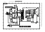
Page 30: ... 3607 D5 3608 D4 3609 D4 3610 D5 3612 E5 3614 D5 3615 D4 3617 D5 3618 D4 3619 D5 3624 D5 3625 D5 3634 D5 3635 D5 3801 D3 3802 D3 3808 C2 3832 D1 3833 D1 3834 C2 3836 C2 3837 C2 3839 C2 3981 B1 3982 B1 5001 E5 5002 E5 5201 E4 5202 E3 5241 E5 5242 E5 5401 B4 5403 B5 5406 B4 5408 A5 5410 C6 5444 C4 5445 A5 5471 C6 5500 B2 5501 B2 5502 B2 5505 B4 5520 A4 5521 A3 5560 A4 5561 B4 5562 B4 5563 A4 5602 D4...

Page 31: ...232 E3 3233 E1 3234 E3 3236 E1 3237 E1 3238 E1 3239 E1 3240 E1 3241 E2 3242 E3 3245 E2 3246 E3 3247 C2 3248 E3 3254 E2 3256 C3 3257 E2 3258 E2 3259 D2 3261 E1 3410 B1 3413 B2 3418 C2 3419 C2 3420 C1 3422 C1 3423 C1 3426 C2 3431 B2 3520 B4 3522 B4 3524 B4 3525 B4 3528 B3 3529 B4 3530 B4 3531 B4 3540 B3 3541 B3 3542 B3 3545 B3 3546 C3 3548 C3 3552 C4 3559 C3 3562 B3 3563 C3 3566 C4 3567 B3 3568 B3 3...

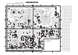
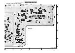
Page 32: ...EN 32 L01 2A AB 7 Circuit Diagrams and PWB Layouts Layout Mono Carrier Part 1 Bottom Side Part 1 F_12751_002a eps 060105 ...

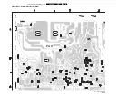
Page 33: ...Circuit Diagrams and PWB Layouts EN 33 L01 2A AB 7 Layout Mono Carrier Part 2 Bottom Side Part 2 F_12751_002b eps 060105 ...

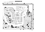
Page 34: ...EN 34 L01 2A AB 7 Circuit Diagrams and PWB Layouts Layout Mono Carrier Part 3 Bottom Side Part 3 F_12751_002c eps 060105 ...

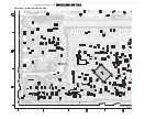
Page 35: ...Circuit Diagrams and PWB Layouts EN 35 L01 2A AB 7 Layout Mono Carrier Part 4 Bottom Side F_12751_002d eps 060105 Part 4 ...

Page 36: ...I311 E5 I312 F3 I313 F3 I314 E4 I316 E4 I318 D6 I320 F6 I321 D5 I322 D3 I323 D3 I324 D4 Pin 8 Pin 11 Pin 5 TO Green Pin 7 Ground 100MHz FOCUS Pin 6 2n2 I326 C4 I329 G3 I331 B5 I332 B3 I333 C3 I334 B4 I335 B5 I336 A4 I337 E7 I338 F6 I339 G3 I341 E6 I343 G4 136V 5341 127V 1V8 9 Pin Blue 2V4 3K9 136V 21 1R2 Green VG1 6344 BAS216 OLDGND I336 I333 V15 10 V12 1n 2344 OLDGND H2 I339 OLDGND OLDGND 1 2 3 4...

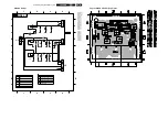
Page 37: ... 3327 A2 3334 A2 3336 A2 3337 A2 3341 A1 3347 A2 3348 A1 3349 A1 3350 A1 5341 A1 5342 A2 6311 A2 6321 A2 6331 A2 6341 A2 6342 A2 7311 A2 7312 A2 7313 A2 7321 A2 7322 A2 7323 A2 7331 A2 7332 A2 7333 A2 9300 A2 9301 A1 9302 A2 9303 A2 9304 A2 Layout CRT Panel Bottom View F_12751_004 eps 060105 3139 123 5356 8 2313 A1 2323 A1 2331 A1 2344 A1 3311 A1 3312 A1 3313 A1 3321 A1 3322 A1 3323 A1 3331 A1 333...

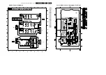
Page 38: ...3 4 1 2 3 4 A B C D E A B C D E 0250 A B1 9155 0250 B C1 0250 C A1 0251 B4 0252 B1 0253 A4 0261 D4 1152 A2 1153 C2 1154 B2 2171 C3 2172 B3 2173 B2 2174 C2 2175 B1 3150 C3 3151 C3 3152 B3 3153 B3 3155 A3 9152 5010 B3 6161 A3 9152 B2 9153 B3 9155 B3 9153 330p 2175 330p 2171 330p 2172 5010 0261 1 2 3 4 5 6 2174 2173 0252 1 2 3 4 3 0253 1 2 3 0251 1 2 1 2 3 75R 3155 1152 0250 C 0250 B 4 5 6 6161 BZX79...

Page 39: ... A B C D E A B C SG06 0252 B2 0253 A5 0254 D2 0255 D5 0261 C5 2171 C4 2172 B4 2173 B3 2174 C3 2176 E3 2177 E2 2178 E3 2179 D2 3150 C3 3151 C3 3152 B3 3153 B3 3155 A3 3156 D3 3157 E3 6161 A3 9153 B3 9155 B4 SG02 A3 SG03 C3 SG04 B3 SG06 E3 SG07 E3 4 1 2 3 4 0255 1 2 3 0251 1 2 3 0252 0253 1 2 3 3157 9155 3156 0254 1 2 3 4 5 2174 2177 100u 2176 100u 2179 3 4 5 6 7 8 9 2178 2172 330p 0232 1 2 2173 1 2...

Page 40: ...EN 40 L01 2A AB 7 Circuit Diagrams and PWB Layouts Personal Notes Personal Notes ...

Page 41: ...attern is a black picture blank screen on CRT without any OSD info 7 Set the channel of the oscilloscope to 50 V div and the time base to 0 2 ms external triggering on the vertical pulse 8 Ground the scope at the CRT panel and connect a 10 1 probe to one of the cathodes of the picture tube socket see diagram B 9 Measure the cut off pulse during first full line after the frame blanking see Fig 8 2 ...

Page 42: ... 59A 0 247 65 0 210 80 9 14PT2012 59B 0 247 65 0 210 80 9 14PT2012 59C 0 247 65 0 210 80 9 14PT2012 65R 0 247 65 0 210 80 9 14PT2401 94R 192 215 65 0 194 80 0 14PT2411 94R 192 215 65 0 194 80 0 15PT2301 67R 160 215 65 168 246 144 44 15PT2301 71R 160 215 65 162 246 144 36 15PT2301 74R 160 215 65 168 246 144 44 15PT2302 56A 160 247 65 168 246 144 44 15PT2302 57R 160 247 65 168 246 144 44 15PT2302 65...

Page 43: ...nding order starting from program 1 Default setting 0 OP15 LNA0 Auto Picture Booster is not available or not applicable 1 Auto Picture Booster is available Default setting 0 OP16 FM_RADIO0 FM radio feature is disabled or not applicable 1 FM radio feature is enabled Default setting 0 OP17 PHILIPS_TUNER0 ALPS MASCO compatible tuner is in use 1 Philips compatible tuner is in use Default setting 0 OP2...

Page 44: ...pplicable 1 Wake up clock feature is enabled Default setting 1 OP65 SMART_CLOCK0 Smart Clock Using Teletext and Smart Clock Using PBS is disabled or not applicable 1 Smart Clock Using Teletext and Smart Clock Using PBS is enabled For NAFTA menu item AUTOCHRON is present in the INSTALL submenu Default setting 0 OP66 SMART_SURF0 Smart Surf feature is disabled or not applicable 1 Smart Surf feature i...

Page 45: ...G 3 DELTA WARM B 2 8 3 4 Geometry The geometry alignments menu contains several items to align the set in order to obtain correct picture geometry Figure 8 9 Connect an external video pattern generator to the aerial input of the TV set and input a crosshatch test pattern Set the generator amplitude to at least 1 mV and set frequency to 475 25 MHz PAL SECAM or 61 25 MHz NTSC 1 Set Smart Picture to ...

Page 46: ... sets Figure 8 12 8 3 5 Audio Figure 8 13 No alignments are needed for the audio sub menu Use the given default values AT Default value is 8 AF M Default value is 44 A2T Default value is 250 QSS OFF for mono sets ON for stereo sets FMI OFF for mono sets ON for stereo sets S A M H O R I Z O N T A L V E R T I C A L H P X X H B X X H S H X X CL 16532008_059 pdf 220501 S A M H O R I Z O N T A L V E R ...

Page 47: ...The tuning system features 100 channels with on screen display The main tuning system uses a tuner a microcomputer and a memory IC mounted on the main panel Also in some type numbers an FM radio is implemented with 40 pre set channels The microcomputer communicates with the memory IC the customer keyboard remote receiver tuner signal processor IC and the audio output IC via the I2 C bus The memory...

Page 48: ...ON RF ANT FM ANT EXT AUDIO INPUT 7801 FM FMR AUDIO SOURCE SELECTION CONTROL EXT AUDIO OUT 7861 7831 7834 7835 7209 7210 7901 10 1000 0265 11 1 1 1 AGC 1200 1202 18 19 22 23 33 47 24 25 24 38 INT_CVBS EXT_CVBS 40 42 16 17 15 30 68 I2C 50 53 EXT RGB YUV INPUT 56 58 7330 EHT 7460 H EW V V 7471 7602 7200 SIF VIF POWER SUPPLY CL 16532008_039 eps 220501 AUDIO AMPL SAW FILTER SAW FILTER SOUND IF DEMOD AU...

Page 49: ...chroma band pass filter for PAL NTSC processing or the cloche filter for SECAM processing is switched on The selected luminance Y signal is supplied to the horizontal and vertical synchronisation processing circuit and to the luminance processing circuit In the luminance processing block the luminance signal goes to the chroma trap filter This trap is switched on or off depending on the colour bur...

Page 50: ...7 V The voltage on pin 54 is normally 3 3 V limiter not active During set switch off the black current control circuit generates a fixed beam current of 1 mA This current ensures that the picture tube capacitance is discharged During the switch off period the vertical deflection is placed in an over scan position so that the discharge is not visible on the screen 9 3 7 RGB Amplifier From outputs 5...

Page 51: ...3532 to pin 8 The operating voltage for the driver circuit is also taken from the hot side of this transformer The switching regulator IC 7520 starts switching the FET on and off to control the current flow through the primary winding of transformer 5520 The energy stored in the primary winding during the on time is delivered to the secondary windings during the off time The MainSupply line is the...

Page 52: ... the diode starts to conduct and the inductive current IL will decrease In other words the transformer will be demagnetised When the inductive current has become zero the next interval begins Interval 4 t3 t t00 resonance time In the fourth interval the energy stored in the drain capacitor CD will start to resonate with the inductance LP The voltage and current waveforms are sinusoidal waveforms T...

Page 53: ...vel of 75 mV This fixed VCO level is called VVCO start The frequency will be reduced in relation to the VCO voltage between 75 mV and 50 mV at levels larger than 75 mV Ctrl voltage 1 425V the oscillator will run on maximum frequency foscH 175 kHz typically At 50 mV VVCO max the frequency is reduced to the minimum level of 6 kHz Valley switching is still active in this mode Minimum Frequency mode M...

Page 54: ...on the load t3 Charge of VCC when gate drive is inactive The third interval starts when the UVLO is reached The internal current source charges the VCC capacitor also the soft start capacitor is recharged Once the VCC capacitor is charged to the start up voltage the driver is activated and a new burst cycle is started Figure 9 15 9 6 3 Protection Events The SMPS IC 7520 has the following protectio...

Page 55: ...used to control other signal processing functions like video processing sound IF vision IF synchronisation etc 9 7 3 User Interface There are two control signals called KEYBOARD_protn and IR Users can interact either through the Remote Control transmitter or by activation of the appropriate keyboard buttons The L01 uses a remote control with RC5 protocol The incoming signal is connected to pin 67 ...

Page 56: ... fused resistor 3411 is built in for double protection In case of a high voltage appearing across capacitor 2401 dependent of the tube size which is high enough to trigger zener diode 6401 into conduction transistor TS7606 in A7 diagram will conduct and UOC is triggered to shut down the power supply I2 C protection to check whether all I2C IC s are functioning In case one of these protections is a...

Page 57: ...AL Phase Alternating Line Colour system mainly used in West Europe colour carrier 4 433619 MHz and South America colour carrier PAL M 3 575612 MHz and PAL N 3 582056 MHz PCB Printed Circuit board PIP Picture In Picture PLL Phase Locked Loop Used for e g FST tuning systems The customer can give directly the desired frequency POR Power On Reset Progressive Scan Scan mode where all scan lines are dis...

Page 58: ...V 2520 4822 126 14585 100nF 10 50V 2521 4822 124 81151 22µF 50V 2522 4822 126 14585 100nF 10 50V 2523h 4822 126 13862 1 5nF 10 2kV 2525 5322 122 34099 470pF 10 63V 2526 5322 122 31647 1nF 10 63V 2527 5322 122 34099 470pF 10 63V 2540 4822 126 13188 15nF 5 63V 2541 4822 122 33177 10nF 20 50V 2560h 4822 126 13449 1nF 10 2kV 2561 4822 124 42336 47µF 20 160V 2562 5322 122 32331 1nF 10 100V 2563 5322 12...

Page 59: ...102 1kΩ 2 0 25W 3946 4822 051 20822 8 2kΩ 5 0 1W 3947 4822 117 10833 10kΩ 1 0 1W 3948 4822 117 10834 47kΩ 1 0 1W 3949 4822 116 83933 15kΩ 1 0 1W 3950 4822 051 20561 560Ω 5 0 1W 3951 4822 051 20391 390Ω 5 0 1W 3981 4822 116 52206 120Ω 5 0 5W 3982 4822 116 52206 120Ω 5 0 5W 4xxx 4822 051 10008 Jumper 1206 4xxx 4822 051 20008 Jumper 0805 b 5001 4822 157 51216 5 6µH 5002 3198 018 18270 820nH 10 5201 4...

Page 60: ... BF422 7313 4822 130 41646 BF423 7321 4822 130 41782 BF422 7322 4822 130 41782 BF422 7323 4822 130 41646 BF423 7331 4822 130 41782 BF422 7332 4822 130 41782 BF422 7333 4822 130 41646 BF423 Side AV Panel E E1 Various 0232h 4822 267 31014 Headphone socket 0250 2422 026 04742 Socket 3 x cinch g 2171 4822 126 13512 330pF 10 50V 2172 5322 122 32311 470pF 10 100V 2172 4822 126 13512 330pF 10 50V 2173 53...

Page 61: ...anual xxxx xxx xxxx 1 Chapter 7 PWB Layouts of Mono Carrier replaced by latest versions Chapter 7 PWB Layouts of CRT Panel replaced by latest versions Links in Table Of Contents and chapter indexes added in the text chapters Some small text and layout changes are made in the text chapters ...

Page 62: ...Revision List EN 62 L01 2A AB 11 ...

Reviews: