background image

1 - 6

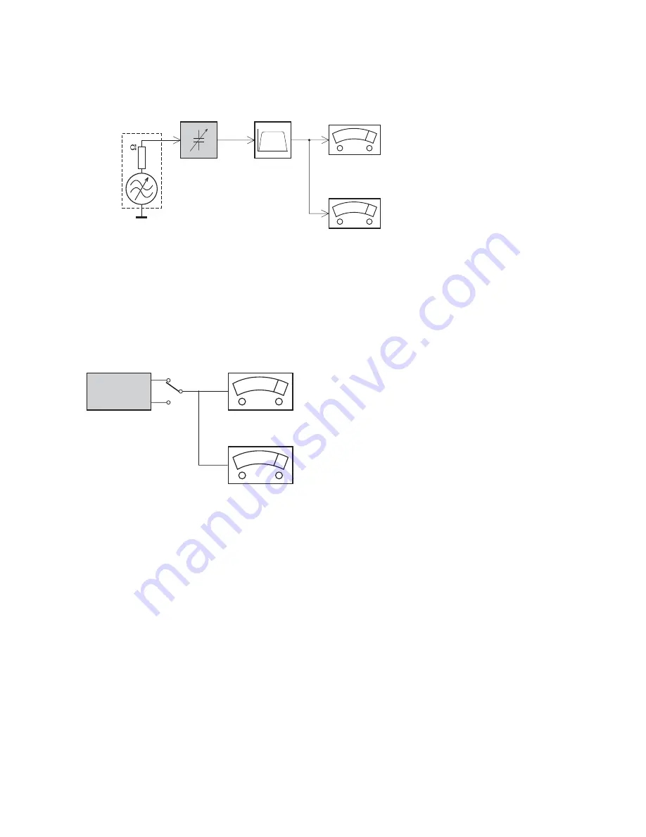
LEVEL METER

e.g. Sennheiser UPM550

with FF-filter

S/N and distortion meter

e.g. Sound Technology ST1700B

L

R

DUT

CD

Use Audio Signal Disc
(replaces test disc 3)

SBC429  4822 397 30184

Bandpass

250Hz-15kHz

e.g. 7122 707 48001

LF Voltmeter

 e.g. PM2534

DUT

RF Generator 

e.g. PM5326

S/N and distortion meter

 e.g. Sound Technology ST1700B

Use a bandpass filter to eliminate hum (50Hz, 100Hz) and disturbance from the pilottone (19kHz, 38kHz).

Ri=50

Tuner FM

MEASUREMENT SETUP

Summary of Contents for HTS8562/98

Page 1: ...erlands Subject to modification BD Home Theater System Version1 1 TABLE OF CONTENTS Location Of PCB Boards 1 2 Versions Variation 1 2 Measurement Setup 1 6 Specifications 1 3 Service Aids 1 7 ESD Safety Instruction 1 8 Lead free Soldering Information 1 9 Setting Procedure Repair Instructions 2 Disassembly Instructions Service Positions 3 Block Wiring 4 Diagram Quick Strart Guide 5 MAIN VFD USB MP3...

Page 2: ...WILE KEY STBY Board BD Board Type Versions Board in used HTS8562 C C Bd 12 SERVICE SCENARIO MATRIX 12 x x Power Board Bd Board Level Replacement C Component Level Repair Wireless ready x MAIN PCB KARAOKE PCB POWER PBC WIFI PCB BD PCB MP3 USB PCB VFD PCB KEY PCB STANDBY PCB WIRELESS PCB Ipod Dock x HTS8562 98 x x x x HTS8562 C C Bd 98 ...

Page 3: ...you have a high definition TV your home theater allows you to play your video files with Resolution 1920 x 1080 pixels at Frame rate 6 30 frames per second avi files in AVI container Media formats AVCHD BD BD R BD RE BD Video DVD Video DVD R RW DVD R RW DVD R R DL CD R CD RW Audio CD Video CD SVCD Picture files MP3 media WMA media DivX PlusHD media USB storage device Audio codec Video codec Bit ra...

Page 4: ... container Audio codec Video codec Bit rate Dolby MPEG MP3 AAC HE AAC MPEG 1 MPEG 2 20Mbps peak 40Mbps MPEG 4 ASP 10Mbps max H 264 AVC HP 4 1 4 0 MP 3 2 3 1 3 0 20Mbps peak 40Mbps mkv files in MKV container Input sensitivity AUX1 1000 mV Music iLink 500 mV Video Signalsystem PAL NTSC HDMI output 480i 576i 480p 576p 720p 1080i 1080p 1080p24 Audio S PDIFDigital audio input Coaxial IEC 60958 3 Optica...

Page 5: ... Hz Dimensions WxHxD 196 x 395 x 342 mm Weight 4 9 kg Cable length 3 m Speakerimpedance 5 ohm Speaker drivers Dimensions WxHxD small speakers 97 x 301 x 120mm Weight 1 5kg Cable length front speakers 4m Cable length rear speakers 10m Remote control batteries 2 x AAA R03 1 5V Laser LaserType Diode InGaN AIGaN BD AIGaInP DVD CD Wave length 405 7nm 7nm BD 655 10nm 10nm DVD 790 10nm 20nm CD Output pow...

Page 6: ...Signal Disc replaces test disc 3 SBC429 4822 397 30184 Bandpass 250Hz 15kHz e g 7122 707 48001 LF Voltmeter e g PM2534 DUT RF Generator e g PM5326 S N and distortion meter e g Sound Technology ST1700B Use a bandpass filter to eliminate hum 50Hz 100Hz and disturbance from the pilottone 19kHz 38kHz Ri 50 Tuner FM MEASUREMENT SETUP ...

Page 7: ...x driver set T6 T20 4822 395 50145 Torx driver T10 extended 4822 395 50423 Compact Disc SBC426 426A Test disc 5 5A 4822 397 30096 SBC442 Audio Burn in test disc 1kHz 4822 397 30155 SBC429 Audio Signals disc 4822 397 30184 Dolby Pro logic Test Disc 4822 395 10216 SERVICE AIDS HANDLING CHIP COMPONENTS ...

Page 8: ...ore returning set to customer perform a leakage current measurement test from all exposed metal parts to earth ground to assure no shock hazard exist The leakage current must not exceed 0 5mA CLASS 1 LASER PRODUCT 3122 110 03420 GB Warning Invisible laser radiation when open Avoid direct exposure to beam S Varning Osynlig laserstrålning när apparaten är öppnad och spärren är urkopplad Betrakta ej ...

Page 9: ...duce heat Mix of lead free solder alloy parts with leaded solder alloy parts is possible but PHILIPS recommends strongly to avoid mixed solder alloy types leaded and lead free If one cannot avoid or does not know whether product is lead free clean carefully the solder joint from old solder alloy and re solder with new solder alloy SAC305 Use only original spare parts listed in the Service Manuals ...

Page 10: ...ftware Please wait Software updates for this player have been found Do you want to upgrade Cancel Start f Select Start press OK button on R C Software upgrade will take 5 minutes Do not switch off Package version 000025 0 Software BE 80 Software FE Completed Software MCU1 Software Dock Software MCU3 Software upgrade will take 5 minutes Do not switch off Package version 000025 0 Software BE Complet...

Page 11: ...ve Blu ray Loader is needed to be send back to supplier for failure analysis and to support backcharging evidence K911 K 11 K 16 Top side view of OPU Bottom side view of OPU The ESD protection points on the top of board CAUTION This information is confidential and may not be distributed Only a qualified service person should reprogram the Region Code Software upgrade will take 5 minutes Do not swi...

Page 12: ...jointpart yes Check IC3002 their conjointpart F Coaxial inFunctionNo Sound Check Signal Source outputwhether OK No InsteadSignalSource yes Check IC 3003 Pin2 inputsignal whether OK No Check JK3001 andIC3003 Pin2 conjointpart yes Check IC 3003 and conjointpart G Optical In No Sound Check IC 3003 Pin1 input signalwhether OK No Check JK3001 Pin1 3 3V a nd IC3003 Pin1 conjointpart yes Check IC 3003 an...

Page 13: ... supply after removing the Tray Cover Note If this is not possible the BD Tray has to be open manually Take a mini screw driver about 2mm diameter and make a marking 24mm from the tip as shown in figure 4 Place the set on its side insert the mini screw driver till the marking and slide it towards the right as shown in figure 3 until the Tray moves out of the Front Panel 2 Return the set to its upr...

Page 14: ... 12 E F WARNING This cable is to be use for servicing only Not to be use in the set assessmbly after service as it may cause safety issue To be remove and replace with original cable after servicing Note When you repaire Main Board this VFC cable must be replaced by below VFC cable as shown in figure 11 Figure 10 VFC120230 250R Figure 11 G Figure 12 Dismantling of the VFD Board 1 Loosen 2 screws H...

Page 15: ... MP3 USB Board 1 Remove the Display Lens as shown in figure 16 2 Loosen 2 screws K on the top of MP3 USB board as shown in figure 17 K Figure 17 Dismantling of the KARAOKE Board 1 Loosen 2 screws L on the top of KARAOKE board as shown in figure 18 L Figure 18 Dismantling of the WIRELESS Board 1 Loosen 2 screws O at the back panel as shown in figure 19 O Figure 19 Service Position A MAIN Board Serv...

Page 16: ...4 1 4 1 BLOCK DIAGRAM ...

Page 17: ...4 2 4 2 WIRING DIAGRAM V7 V9 V5 V1 V4 V2 V8 V6 V3 ...

Page 18: ...es from the internet site of Philips Consumer Care Center www support philips com Quick start guide www philips com welcome Register your product and get support at www philips com welcome Register your product and get support at SUB WOOFER SUB WOOFER FRONT CENTER FRONT CENTER REAR LEFT REAR LEFT FRONT RIGHT FRONT RIGHT FRONT LEFT FRONT LEFT REAR RIGHT REAR RIGHT STS9501 ...

Page 19: ...Pod OPTICAL COAXIAL HDMI IN 1 HDMI IN 2 ANTENNA LAN VIDEO OUT VIDEO SD CARD FOR VOD BD LIVE ONLY TO TV FRONT LEFT SUB WOOFER FRONT RIGHT REAR RIGHT FRONT CENTRE REAR LEFT FRONT CENTER REAR LEFT SUB WOOFER FRONT RIGHT FRONT LEFT REAR RIGHT HDMI OUT ARC TO TV HDMI ARC HDMI IN 1 HDMI IN 2 HDMI OUT HDMI OUT HDMI IN HDMI ARC HDMI OUT ARC TO TV ANTENNA AC MAINS ...

Page 20: ...5 3 5 3 1 2 SUB WOOFER FRONT LEFT FRONT CENTER FRONT RIGHT REAR RIGHT REAR LEFT MUSIC iLINK MUSIC iLINK 1 TV HDMI 2 HOME THEATER 3 HOME THEATER ...

Page 21: ...5 4 5 4 3 2 1 3 2 MUSIC iLINK 1 MUSIC iLINK 2 3 1 DOCK for iPod 3 1 2 U N L O C K T S U J D A O T E D I L S TV TV HOME THEATER 1 2 ...

Page 22: ... 6 5 Circuit Diagram part five 6 6 Circuit Diagram part six 6 7 PCB Layout Top View 6 8 PCB Layout Bottom View 6 9 INTERNAL IC DIAGRAM CS495313 CVZ INTERNAL IC DIAGRAM STM32F100VCT6 STC TMR1 TMR2 PLL 12Ch Audio In 6Ch SACD In S PDIFS PDIF 16Ch PCM Audio Out Ser i al Cont r ol 2 Ser i al Cont r ol 1 Paral i el Cont r ol UART G PIO Deoug 32 b it DSP B 32 b it DSP A P X Y P X Y Ext Mem ory Cont r oll...

Page 23: ...LI D4 SU B _A SU B _A TP5016 C 5136 1000U 50V ZD 5001 NC R5121 330 C 5142 100U 10V C 5143 220U 10V 5V Q5003 2SD882 R5126 4K7 R5127 4K7 POWER_ C R5068 NC 7 5 6 B 8 IC 5006B IC _JRC 4558 3 2 1 B 4 IC 5006A IC _JRC 4558 R5106 NC R5110 NC R5116 NC R5052 NC C5103 104 12V R5104 NC C5104 NC R5117 NC P_DE T C5140 10U 16V C5141 NC R5118 1K R5119 120 R5 103 NC R5107 NC C5101 NC C5139 NC R5 113 NC R5108 NC R...

Page 24: ...BR L LRCK SR L VCC3 3 V 5V INT GND SDA GND BCK NC GND 1 2 3 4 5 6 7 8 9 10 11 12 13 14 JK 1001 CN14 20 BC K_ W LRCK _W TSD3_W SB R L MCLK _W TO HTS wireless TX PCB C001 104 Q104 Q105 23KVESD Q106 23KVESD Q107 23KVESD Q108 23KVESD 1 2 3 4 5 6 7 8 9 10 11 12 13 CN103 CN13 20L 5V GND GND GND LRCK IR Q BC K RS T TSD3 SCL NC SDA GND LRCK _W GPIO3_IRQ INT BC K_ W RESE T TSD3_W SCL_ W SDA_W LRCK _W GPIO3...

Page 25: ...0 RX P0 1 RX 1 RX N0 2 AGN D 4 RX 2 RX P1 5 RX 3 RX N1 6 AD 0 CS 7 AD 1 CDIN 8 SCL CCL K 9 SDA CDOUT 10 XT I 11 XT O 12 IL RCK 13 IS CL K 14 SD IN 15 GPO0 16 GPO1 17 GOP2 18 VD _FIL T 20 DGND 21 SDOUT2 23 OSCLK2 24 OLRCK 2 25 TDM_ IN 26 SDOUT 1 27 OSCLK1 28 OLRCK 1 29 GPO3 30 RMCK 31 RS T 32 N C 33 OE2 19 OE1 1 A0 2 A1 3 A2 4 A3 5 A4 6 A5 7 A6 8 A7 9 Y7 11 Y6 12 Y5 13 Y4 14 Y3 15 Y2 16 Y1 17 Y0 18...

Page 26: ...622 R171 33 HDMI_ MCLK HDMI_ SCLK HDMI_ LRCK HDMI_ D0 HDMI_ D1 HDMI_ D2 HDMI_ D3 SPDIF_OUT_ 7622 BK 5V R183 47K CS 1 S0 2 WP 3 GND 4 S1 5 SCK 6 HOL D 7 VC C 8 IC105 25LC040A SPI_SCK SPI_CS SPI_MOSI SPI_MISO SPI_CS R 184 47K SPI _3 3V SPI _3 3V SPI_MISO SPI_MOSI R167 NC R 186 NC R 185 10K SPI_SCK FB112 100 C192 104 3 3V_M SPI_3 3V R1 89 0 R1 88 0 R1 87 0 D103 IN4148 D104 IN4148 D105 OPT D102 IN4148...

Page 27: ...1 16 PC2 17 PC3 18 VSSA 19 VR EF 20 VR EF 21 VDDA 22 PA0 WK UP 23 PA1 24 PA2 25 PA14 76 PA15 77 PC10 78 PC11 79 PC12 80 PD0 81 PD1 82 PD2 83 PD3 84 PD4 85 PD5 86 PD6 87 V SS_ 3 99 VDD_ 3 100 PD7 88 PB 3 89 PB 4 90 PB 5 91 PB 6 92 PB 7 93 B OOT 0 94 PB 8 95 PB 9 96 PE 0 97 PE 1 98 PB12 51 PB13 52 PB14 53 PB15 54 PD8 55 PD9 56 PD10 57 PD11 58 PD12 59 PD13 60 PD14 61 PD15 62 PC6 63 PC7 64 PC8 65 PC9 ...

Page 28: ...0 C823 22U 50V C824 22U 50V C826 10U 25V R825 470 801 849 C815 102 C825 470P GND_ V VFD_AC_V LED_C_V 1 2 3 4 5 6 CN803 CN6 10L P_ 5V P_ 5V LE D1 1 LE D2 2 LE D3 3 LE D4 4 OSC 5 DOUT 6 DIN 7 CL K 8 STB 9 K1 10 K2 11 VS S 12 VDD 13 VE E 30 SG1 KS 1 14 SG2 KS 2 15 SG3 KS 3 16 SG4 KS 4 17 SG5 KS 5 18 SG6 KS 6 19 SG7 KS 7 20 SG8 KS 8 21 SG9 KS 9 22 SG10 KS 10 23 SG11 KS 11 24 SG12 KS 12 25 GR 1 42 GR 2...

Page 29: ...303 C3 Q304 C3 Q305 C4 Q306 C4 Q307 C3 Q5001 A3 Q5002 A3 Q5003 C3 Q5004 B3 Q5005 B3 Q5006 B3 Q5007 A3 Q802 C1 Q803 C1 R100 B1 R1001 A2 R1002 A2 R1003 A2 R101 A1 R102 A1 R103 A1 R105 A2 R1055 C2 R106 A1 R107 A1 R108 A2 R109 B2 R110 B1 R111 B1 R112 B2 R113 B1 R114 B1 R121 A1 R122 A1 R125 B1 R126 B2 R127 B1 R128 B1 R129 B1 R130 B1 R131 B1 R132 B1 R133 B1 R134 B1 R135 A1 R136 B1 R137 A1 R138 B1 R139 B...

Page 30: ...9 A4 C5020 A4 C5021 A4 C5022 A4 C5023 A4 C5024 A4 C5025 B4 C5026 B4 C5027 C4 C5028 C4 C5029 B4 C5030 B4 C5031 A4 C5032 A4 C5033 B4 C5034 B4 C5035 B4 C5036 B4 C5066 C3 C5072 C4 C5073 B4 C5106 B3 C5144 C3 C5146 B3 C5147 C3 C5149 C3 C5151 B3 C5158 B3 C5160 B3 C5161 B3 C5162 B3 C5163 C3 C5164 C3 C5165 B3 C5166 C3 C5167 B3 C5168 C3 C5170 B4 C5171 C3 C5172 C3 C5173 B4 C5174 B4 C5187 A3 C5188 A3 C5189 A3...

Page 31: ...1 POWER BOARD TABLE OF CONTENTS Internal IC Diagram 7 1 Circuit Diagram 7 2 PCB Layout Top View 7 3 PCB Layout Bottom View 7 4 V REF REF CATHODE ANODE INTERNAL IC DIAGRAM AZ431 INTERNAL IC DIAGRAM SSC620S SOP ...

Page 32: ...2 IC905 B4 L904 C3 L905 B3 L906 C3 L907 A3 L908 A3 LF901 B1 LF901 B1 LF902 B1 LF902 B1 NTC901 C1 Q901 C2 Q902 A2 Q903 A2 Q904 C3 Q906 C3 Q907 C3 Q909 B3 Q910 B3 Q910 B3 Q911 B3 Q911 B3 Q912 C3 Q913 B4 Q915 B3 Q917 C3 Q995 B4 R901A C4 R902 B1 R902A C4 R903 B1 R904 B1 R905 B1 R909 A3 R910 A4 R911 B4 R912 B1 R914 A4 R915 A1 R916 A1 R917 A1 R918 A1 R919 A4 R920 C2 R922 C3 R923 C4 R924 B1 R925 C3 R926 ...

Page 33: ...C3 D917 B4 D918 A2 D919 A3 D922 B3 D923 B3 D924 D3 D928 C4 D930 C2 D931 B2 F901 D1 GT902 C1 GT903 A2 GT904 B2 GT905 C2 IC904 A3 IC904 A3 IC905 C4 J902 C1 J903 B2 J904 C2 J905 A3 J906 A2 J908 C2 J909 A3 J910 A3 J911 A4 J912 A4 J913 A3 J914 A4 J915 B4 J916 B4 J917 B4 J918 B4 J919 C4 J920 C4 J921 D3 J922 D3 J923 D4 J924 D4 J925 B4 J926 B3 J927 C4 J928 A2 J929 C2 J930 D2 J931 D2 L904 B4 L905 A4 L906 A...

Page 34: ...D4 R911 B4 R914 D4 R915 B2 R916 B1 R917 A2 R918 A1 R919 D4 R920 A2 R921 A4 R922 C3 R924 C1 R925 D4 R926 C4 R927 C3 R928 C3 R930A A2 R930B A2 R930C A2 R930D A2 R930E A2 R930F A2 R930G A2 R930H A2 R932 C3 R933 A2 R934 D1 R935 A2 R937 A2 R938 B4 R938A A4 R939 B4 R942 B2 R945A C3 R945B C3 R945C C3 R945D C3 R945E C3 R945F C2 R945G C2 R945H C2 R945I C2 R945J C2 R945K C4 R945L C4 R945M C4 R945N C4 R945O ...

Page 35: ...8 1 8 1 BD BOARD TABLE OF CONTENTS Block Diagram BD Board 8 1 Voltages for connector pin 8 2 Waveforms for measure point 8 3 BLOCK DIAGRAM ...

Page 36: ...O 2 11V 1 92V 2 54V RFO 3 25V 3 04V 0V LDO_CLK 3 25V 3 02V 3 3V LDO_SEN VCC_PDIC GND 3 25V 0V 1 65V GAIN_SW GND 0V 0V 4 54V BD_LD GND 1 55V 1 23V 1 48V AUX1 VCC_HFM 0V 0V 0 08V MDI_BD 0 15V 0V 0 15V DVD_VR 0V 0V 0V CD_VR 0V 0V 0V CD_HFM GND 1 HA500 from BD board connect to main board PIN NO PIN Assign 1 2 IPOD_TXD 3 IPOD_RXD 4 IPOD_DET_SW 5 IR 6 7 I2C_IRQ 8 9 CEC 10 AMUTE 11 12 SCL 13 SDA 14 15 MC...

Page 37: ... HA500 PIN13_SDA Play BD Disc wave Play BD Disc wave HA500 PIN15_MCLK HA500 PIN17_LRCK Play BD Disc wave Play BD Disc wave qjo qjo3 HA500 PIN2_Ipod_TX Play BD Disc wave HA500 PIN3_Ipod_RX Play BD Disc wave HA500 PIN7_IR VOL up down HA500 PIN5_12C_IRQ Play BD Disc wave Play BD Disc wave HA500 PIN9_CEC HA500 PIN9_CEC ...

Page 38: ...nvu HA500 PIN19_BCK HA500 PIN21_AOSDAT0 Play BD Disc wave Play BD Disc wave HA500 PIN22_AOSDAT1 HA500 PIN23_AOSDAT2 Play BD Disc wave Play BD Disc wave HA500 PIN10_A_MUTE HA500 PIN29_HDMI_ARC HDMI_ARC function wave CN203 Pin3 USBM pin4 USBP USB and WIFI Function wave ...

Page 39: ...9 1 9 1 Mechanical Exploded View Note A1 3 5 8 24 29 33 36 RC MIC FM ...

Page 40: ...10 1 REVISION LIST Version 1 0 Initial release Version 1 1 HTS8562 12 combine with HTS8562 98 ...

Reviews: