background image

HD3620/20

5-13

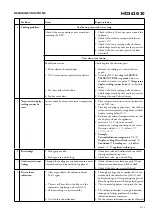
Stepmode

(Press & release
KEG switch)

Test

Stimulus

Response

Remark

0

Show software version

Shows 
software 
version

2 digits.  E.g. 21 = version 2.1

1

Display test

88

88

C

0

!

All segments 
are lit

2

Temperature test

Disconnect NTC (J6) 
from the PCB.
Apply to (J6) below 
resistance values.

NTC simulated value

1.    1 k

 (1%)

2. 10 k

 (1%)

3. 51 k

 (1%)

4. out of range

Display indicates:

1. 

1

C (red color)

2. 

2

C (green)

3. 

3

C (red)

4. 

 (red)

Replace NTC sensor by dummy 
sensor.


J6

19k

5k

3

Pressure measurement

Disconnect Pressure 
sensor (J14) Connect 
external dummy.

Pressure simulated 
value (mV)

1.  0 - 2mV
2.  4 - 6mV
3.  8 - 10mV
4. out of range

Freshness indicates:

1. 

1 (yellow)

2. 

2 (yellow)

3. 

3 (yellow)

4. 

       (yellow)

* Replace pressure sensor and apply 

dummy.


1

J14

4k7

4k7

1k

4k7

4k7

* Depending on the possibilities 

either dummy or pressure can be 
applied for testing.

Apply to the air inlet 
of the sensor or air 
coupling the following 
pressures.

Pressure simulated 
value (mBar)

1.  0       -   300
2.  600   -   900
3.  1200 - 1500
4. out of range

1. 

1 (yellow)

2. 

2 (yellow)

3. 

3 (yellow)

4. 

       (yellow)

* Apply calibrated air pressure to 

the Pressure sensor or by the Air 
coupling hole.

* Depending on the possibilities 

either voltage or pressure can be 
applied for testing.

4

Fan motor low level

1. Fan starts running.
2. Display Off.

Keep KEG switch pressed!!

Fan runs on (80%) level 
Voltage across fan:

~7 - 8.5 Vdc / ~0.25 Vrms

5

Fan motor high level

1. Fan starts running.
2. Display Off.

Keep KEG switch pressed!!

Fan runs on (100%) high level
Voltage across fan:

~10.5 Vdc / ~0 Vrms

REPAIR INSTRUCTIONS

Summary of Contents for HD3620/20

Page 1: ...rference suppression on radio and TV After the product has been repaired it should function properly and has to meet the safety requirements as officially laid down at this moment TECHNICAL INFORMATION Power 70 W Power consumption Cool down period average KEG 23 C 3 C 0 062 kWh Standby period KEG on 3 C 0 042 kWh Voltage 100 120 V 50 60 Hz 200 240 V 50 60 Hz Flow rate 2 L per minute Contents Keg 6...

Page 2: ...d Fan assy Unscrew the 2 screws located on the heat sink The heat sink including Peltier element can now be removed With a small screwdriver the Peltier element can be removed from the heat sink some force maybe needed Before placing the new Peltier element clean the chiller plate and heat sink thoroughly Provide heat sink paste on the heat sink and chiller plate With a plastic comb or plastic lik...

Page 3: ...ycle the pump will start running to get back in the overpressure situation like described before When the Keg present switch has been actuated also the cooling process Peltier element will be started and display functions become visible The temperature is measured by a NTC located near the Keg present plunger The volume indication is based on the principle of a pressure drop measured by the pressu...

Page 4: ...his process will continue over and over again until the appliance will be unplugged See examples Above 2 routines can be used to check the software version and working of the Display If internal parts like NTC Pump Peltier or FAN must be checked also the service test routines see further can be carried out Putting the appliance into Service test mode 1 Disconnect the appliance from mains 2 Remove ...

Page 5: ...yellow 3 3 yellow 4 yellow Replace pressure sensor and apply dummy 1 J14 4k7 4k7 1k 4k7 4k7 Depending on the possibilities either dummy or pressure can be applied for testing Apply to the air inlet of the sensor or air coupling the following pressures Pressure simulated value mBar 1 0 300 2 600 900 3 1200 1500 4 out of range 1 1 yellow 2 2 yellow 3 3 yellow 4 yellow Apply calibrated air pressure t...

Page 6: ...se in the middle the rubber cap 3 Remove the isolation foam under the removed cap until the chiller plate becomes visible Perform the temperature measurement when the unit has reached the room environment temperature 1 Place a contact temperature probe against the chiller plate were the cap was removed 2 Block the air inlet coupling at the Keg side see picture 6 for location Picture 6 3 Plug the a...

Page 7: ... FreshDisp Software detection The KEG present activation switch will give input to the Interface board Checks Is the micro switch function correctly 60 30 C 0 C 0 30 Temperature display reading cannot be trust 1 Display indicates 60 C 2 Display indicates 1 C 3 Display indication not in line with Keg temperature Problem 1 NTC has short circuit 2 NTC has open circuit 3 See chapter SERVICE TESTROUTIN...

Page 8: ...lay reading below 10 C 3 Read out the external temperature meter and the display value of the appliance 4 Subtract a 2 4 C from the external temperature reading and compare the values Deviation aloud 1 C below 3 C 1 C 2 C 5 Example External indication temperature 7 4 C Display reading PerfectDraft system 5 C Conclusion 7 4 reading ext 2 4 offset value 5 C appliance within spec 6 Beer leakage 1 Lea...

Page 9: ...e Description 1 2 3 4 5 6 7 8 9 10 11 12 13 14 15 16 17 18 19 20 21 22 23 24 9965 000 44301 9965 000 44302 9965 000 44303 9965 000 44304 9965 000 26126 9965 000 32659 9965 000 44305 9965 000 26122 9965 000 44306 9965 000 26124 9965 000 26123 9965 000 44307 9965 000 44308 9965 000 44309 9965 000 26117 9965 000 26115 9965 000 26116 9965 000 44310 9965 000 26111 9965 000 44311 9965 000 32874 9965 000...

Page 10: ...HD3620 20 10 13 EXPLODEDVIEW 1 3 2 ...

Page 11: ...HD3620 20 11 13 EXPLODEDVIEW 7 12 13 5 10 11 9 8 6 4 ...

Page 12: ...HD3620 20 12 13 EXPLODEDVIEW 14 ...

Page 13: ...HD3620 20 13 13 EXPLODEDVIEW 18 22 15 20 24 17 21 16 19 23 ...

Reviews: