GC8420
3-8
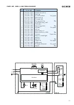
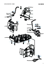
PARTS LIST - IRON & ELECTRICAL DIAGRAM
STAND
IRON
L
N
Stand Electronics
Main Board
Thermal
Fuse
Thermal
Fuse
L
N
E
L
S
N
E
Pump
M
Boiler
Heating
Element
Steam
E-Valve
Ther-
mostat
Trigger
Switch
Iron
Heating
Element
Thermistor
Water level
Hall sensor
Board
Hall
Sensor
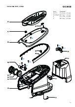
Pos
Service code
Description
1
2
3
4
5
6
7
8
9
10
11
12
13
14
15
16
17
18
19
20
21
4239 021 44370
4239 015 70150
4239 026 31440
4239 021 44410
4239 026 13220
4239 021 48250
4239 014 54680
4239 010 11270
4239 021 49880
4239 026 31500
4239 015 57400
4239 021 31780
4239 021 48320
4239 026 31600
4239 021 48270
4239 010 10110
4239 026 31520
4239 026 31540
4239 014 54690
4239 021 48280
4239 026 31580
Soleplate mounted assy
Ryton ring
Cover SOS molded
Grey purple
Microswitch assy
Thermostat bush
Housing printed assy
Blue
Compression spring (dial)
Dial sounder
Sub-housing printed
Blue
SOS knob
Grey purple
SOS seal
Steam deviator assy
Hose cord cable assy (SOS)
Blue
Grommet Alpine
white
Lamp assy (Amber light)
Hose clip
Inlay SOS
Blue
Trigger SOS
Grey purple
Trigger spring
Thermostat dial printed
Grey purple
Backplate Blue


