


4 .
G Y 5 0 1 r e m o v a l
Remove the main metal side plate (6 screws). Loosen the four
screws securing the top plate together with the valve base, then
remove the screw securing the white insulator to the metal bracket.
Turn the insulator in the two slots until the hole on the captive
side lines up with the head of the fixing rivet, then withdraw the
insulator. Lift out the GY501 valve from the E.H.T. overwind
holder, then withdraw it from the base.
5 .
Line transformer bobbin removal
Remove the main metal side plate (6 screws), and the PD500 and
GY501 valves. Unsolder the E.H.T. lead from the valve holder,
and remove the two plugs from the sockets mounted on the side
plate below the printed panel. Unsolder the four leads from the
tag panels, then remove the four bobbin fixing screws from under-
neath the transformer, allowing the bobbin to be withdrawn through
the bottom of the chassis. When fitting a new bobbin, ensure that
the leads and plugs are replaced correctly, and that the E.H.T.
';,,lead has a smooth soldered joint where it is connected to the valve
,base.
Note.
It is essential that the round metal plate on the top cover
shielding V5003 valve base is always refitted correctly after servicing
the
L.O.P.T.
assembly.
Line transformer fault-finding
The line transformer must not be operated with the screening
cover removed. However, all the tappings on the line trans-
former windings are available externally, via the two 10-way
sockets mounted on the side of the E.H.T. can assembly, and
connections to many components can be made either on the
printed panel or within the valve compartment of the assembly
once the gauze screen has been removed. In cases of arcing due to
breakdown of a component inside the assembly, it may be first
necessary to try to locate approximately where the fault has oc-
curred by noting if any damage is apparent. After replacement of
the line transformer bobbin or any component which has failed
due to breakdown, engineers should ensure that the line output
circuit is operating normally since the breakdown could well be
the symptom of another fault.
The following points should be borne in mind when servicing the
L.O.P.T. assembly.
1.
Boost voltage measurement (590V) gives an immediate know-
ledge of drive to the transformer. Unless the deflection coil
circuit has a fault, normal boost implies correct primary
operation.
2.
A very low boost voltage must indicate either a heavy load on
the line transformer such as a shorted turn, or no drive to the
transformer e.g. open-circuit or no emission in the PL509 or
PY500 valves.
3.
If the boost voltage is fairly normal, then scanning current
exists and the absence of a raster must indicate lack of an
electrode voltage on the C.R.T.
4.
Grid and cathode voltage measurements on the PD500 valve
are very revealing for faults in the shunt stabilising circuit.
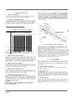
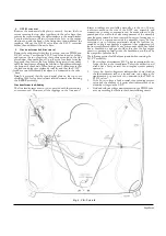
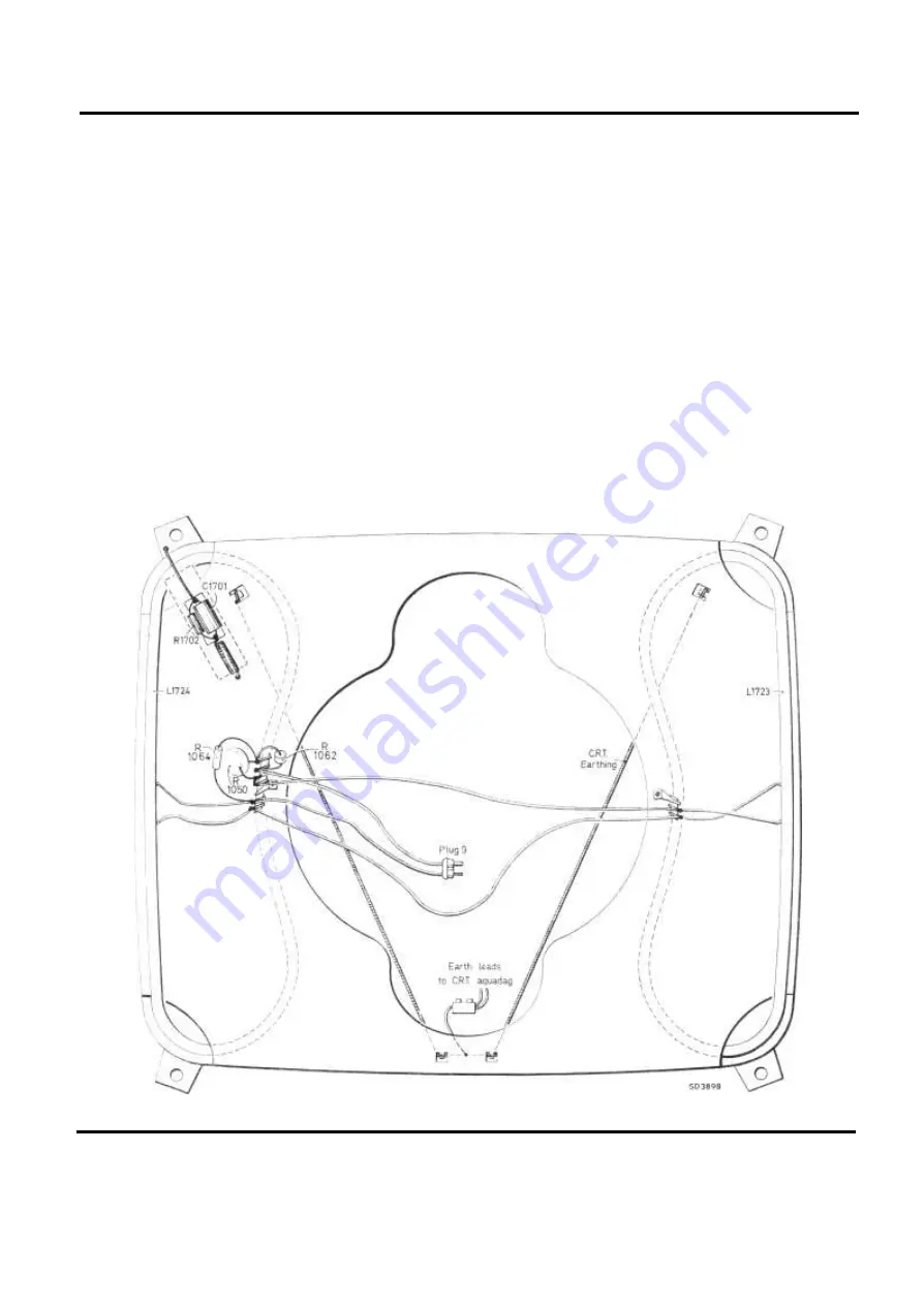
Fig . 4 . C. R. T. shiel d
Page Seven
Summary of Contents for G22K511
Page 3: ...G22K511 G25K512 Page Two ...
Page 12: ...Page Ten ...
Page 14: ...Page Eleven ...
Page 19: ...Page Fifteen ...


