


J - GREY SCALE TRACKING
Dark grey tones
1.
Check that the setting of R7285 is correct (see "Preset adjust-
ments" section H, para. 17).
2.
Disconnect the luminance feed to the C.R.T. and unplug the
I.F. lead from the tuner.
3.
Switch off the red and green guns (switches 18 and 19) and
adjust control (14) until the blue raster is barely visible.
4.
Switch off blue (17) and switch on green (18).
5.
Adjust control (15) until the green raster is barely visible.
6.
Switch off green (18) and switch on red (19).
7.
Adjust control (16) until the red raster is barely visible.
8.
Switch on blue and green guns (17 and 18) and reconnect the
luminance and I.F. leads.
9.
Tune in to a monochrome picture, preferably a stepped
"staircase" pattern containing shades of grey. Check that the
picture has a good neutral grey tone and, if necessary, slightly
readjust any two "G2" controls (14, 15 or 16) to obtain the
correct tone.
White tones
The controls for the setting of the "white tones" in the grey-scale
tracking adjustments require careful setting up which is achieved
during the manufacture of the receiver. The following instructions
are given for guidance since it is necessary to use special test
equipment to obtain precise results.
10.
Using the transmitted picture, adjust R1077 and R1080 (see
Fig. 5) for a neutral white.
K - COLOUR DIFFERENCE OUTPUT ADJUSTMENTS
Firstly check that the grey scale tracking has been correctly set.
1.
Switch to colour bars and adjust controls for normal contrast
and colour.
2.
Switch off red and green guns, and check that the four blue
bars are of equal brightness. If necessary, readjust the contrast
and colour controls. When this check is complete, do not
disturb the front controls until adjustments 3 and 4 are
complete.
3.
Switch off the blue gun and switch on the red. Adjust R7173
for equal brightness of four red bars.
4.
Switch off the red gun and switch on the green. Adjust R7245
to balance the brightness of bar 3 with bars 2 and 4. Then
adjust R7236 to equalise the brightness of bar 1 and bar 4.
Repeat the adjustments of R7245 and R7236 until all 4 green
bars have equal brightness.
L - I.F. ALIGNMENT
1. General
All coils are carefully trimmed and sealed during manufacture.
Normally, complete I.F. alignment should not be necessary, but in
the event of coil replacement, however, some readjustment may be
required and for this reason trimming instructions are given. It
should be noted that most replacement coils are pre-trimmed, and
if any readjustment is required on fitting, this should only
be
slight.
In all cases of trimming, the peak with the core nearest the top of
the former (i.e. away from the printed panel) should be chosen.
Alignment information is given only for a sweep generator method,
and a list of necessary equipment is shown below. A warm-up
period of at least 20 minutes should be allowed for thermal stabi-
lisation of both receiver and test equipment. Leads should be as
short as practicable in order to have least effect on the response
curve. When the sweep generator is connected to the various
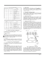
injection points stated, the terminating pad shown in Fig. 9 should
be used.
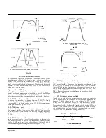
The adjustment of certain vision I.F. coils will affect both luminance
and chrominance response curves. Consequently, a double beam
oscilloscope is recommended in order that both curves may be
observed simultaneously. In the event of double beam facilities not
being available however, a single beam 'scope' may be used but
frequent checks of both response curves should be made during
alignment. To avoid stray pick-up from the time bases, remove
FS1109 and the deflection coil plug (plug 6) before proceeding
with alignment.
2. Test equipment required
The following test equipment is essential in order to carry
out the
alignment operations :-
(a)
A V.H.F. sweep generator (3-42MHz) with deviation
variable 0-12MHz, together with an R.F. marker generator.
(b)
An oscilloscope (preferably double beam) for use in conjunc-
tion with the sweep generator.
(c)
Sweep generator terminating pad as shown in Fig. 9.
(d)
Detector unit as shown in Fig. 11.
(e)
Damping unit-1.5KpF capacitor in series with 470 resistor.
(f)
Combined detector and damping unit as shown in Fig. 10.
(g)
6v. battery for bias source.
Fig. II. Detector unit
Test points
Luminance detector - oscilloscope between L2635 and
chassis.
Chrominance detector-oscilloscope between tag 5 of "CAN
E" and chassis.
Sound inter-carrier I.F. response - oscilloscope between
R2073/122524 and chassis.
Sound inter-carrier I.F. "S" curve - oscilloscope between
R2072/C2022 and chassis.
3rd vision I.F.-collector of T2143.
Chroma. bandpass-oscilloscope to R7156/R7159 and
chassis via detector unit shown in Fig. 11.
Tuner I.F. injection point-remove the tuner from the
cabinet (see section F, para. 4). Remove the _screw which
couples the switch bar to the push-button mechanism, then
push the switch bar into the tuner to its fullest extent in
order to engage the I.F. test position, and fully depress the
second push-button (from the tag strip side). Access to the
I.F.
injection point is now achieved by inserting a suitably
insulated metal probe into the hole in the mounting plate
adjacent to the second push-button. When reconnecting
the switch bar to the mechanism, set the second button to
the,`4-5 ' position and depress. Pull out the switch bar to its
fullest extent and refit the screw, making sure the coupling
bracket is held against the shoulder of the switch bar, which
should now be held fully extended and under tension.
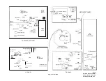
Chassis
503402
I•SKP
47
w
v
-
o-
To TP7
75
8)K p
I
-1"
◼
7) T
UN
EIR
CHASSIS
Fig. 9. Terminating pad
R7156/ R7159
0A81
100K
1K5p
To
oscilloscope
SD3934
1.5Kp•
Collect
or
of
32163
•
Chasss
0A81
SD3935
Fig. 10. Damper/detector unit
To
Oscilloscope
3.
TP1
TP2
TP3
TP4
TP5
TP6
TP7
Page Twelve
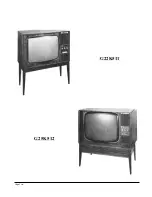
Summary of Contents for G22K511
Page 3: ...G22K511 G25K512 Page Two ...
Page 12: ...Page Ten ...
Page 14: ...Page Eleven ...
Page 19: ...Page Fifteen ...


