background image

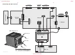
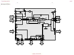
MIDDLE

BASS

VOLUME 2

FADER

MUTE

LOGIC CONTROL

DIGITAL SUPPLY

ANALOG SUPPLY

MUTE CONTROL

I2C INTERFACE

SOURCE SELECTOR

TREBLE

LOUDNESS

VOLUME

IN GAIN

MUTE

FADER

VOLUME 2

BASS

MIDDLE

TREBLE

LOUDNESS

VOLUME

IN GAIN

CHANNEL

LEFT

RIGHT-
CHANNEL

1

2

3

4

5

6

7

8

9

10

11

12

13

14

1

2

3

4

5

6

7

8

9

10

11

12

13

14

A

B

C

D

E

F

G

H

I

J

AUX_IN

LINE_OUT

a

BC847B

7527

2528

a

3n3

3515

1K

3522

7529
BC857B

3550

47K

a

120K

3545

1K5

2541

1u

2M2

3558

NJM4560M

7512-A

3

2

1

3564

2K7

4M7

3598

4619

2610

470p

2595

3596

100K

3519

33K

220R

3584

8

NJM4560M

7512-B

5

6

7

3579

4R7

a

3615

5K6

2K2

3582

2618

a

+12A

a

3608

10K

5K6

3611

2511

100n

3K3

3517

7533

BC847B

4K7

3566

3606

220K

YKC21-3440
1526-A

5

4

3

470n

2574

33n

2602

M

10K

a

2K2

3626

1K

a

3K3

3544

3525

2K7

+12A

FE-BT-VK-N

1521

3624

a

22K

3592

2615

150R

2552

47u

1u

2624

+12A

3554

3520

33K

a

a

a

a

a

3589

1n

2579

6514

1N4003

3530

2K2

22p

2524

2591

220u

100K

3533

a

680p

2536

470n

2K2

3529

4K7

3569

2871

22n

4536

100n

2868

2M2

3559

3560

4M7

a

1u

2575

2521

4u7

a

a

4618

a

a

2527

470p

1K2

a

4K7

3570

a

3556

2604

3n3

3613

5K6

a

3580

+IS

3557

a

2K7

82K

33K

3595

a

3618

8K2

4u7

2513

10n

2677

a

3528

1K

15p

100n

2670

1K

3511

2537

220n

2563

15p

2538

150K

3588

5

6

7

4

a

10p

2547

7513-B

NJM4560M

3537

33K

+IS

12K

3687

2608

100n

3577

470R

8K2

3620

a

6512

BZX79-C9V1

2626

220p

2612

1n8

a

12K

3686

2623

1u

3576

220R

3572

4K7

10p

2548

BC847B

7524

a

150K

3551

a

100n

2512

100R

3599

1525-A

YKC21-3440

5

4

3

a

4535

220u

2592

a

47K

3585

a

47u

2593

2641

100u

2549

4u7

+12M

3521

18K

3538

33K

2616

220p

1K

3625

2n2

a

a

a

2544

a

a

D

2535

680p

+12

a

2529

100n

a

220R

3575

150K

a

BC547B

7525

3552

8K2

3617

2543

2n2

2601

33n

4K7

3574

3628

3573

4K7

a

1526-B
YKC21-3440

5

2

1

2614

1n

1u

2869

a

2K2

3K3

3601

a

3531

3591

22K

a

3612

5K6

STEREO_1L

8

STEREO_1R

17

STEREO_2L

9

STEREO_2R

18

STEREO_3L

10

STEREO_3R

15

STEREO_4L

7

STEREO_4R

44

TREBLE_L

1

TREBLE_R

FRONT_R

20

IN_L

2

IN_R

12

LOUD_L

4

LOUD_R

22

MID_IN_L

31

MID_IN_R

23

MID_OUT_L

30

MID_OUT_R

11

MONO

21

MUXOUT_L

3

MUXOUT_R

35

PAUSE

32

REAR_L

29

REAR_R

28

SMEXT

16

AVDD

24

BASS_IN_L

26

BASS_IN_R

25

BASS_OUT_L

27

BASS_OUT_R

38

CLK

39

CREF

19

CSM

37

DATA

36

DGND

13

DIFF_GND_L

5

DIFF_GND_R

14

DIFF_L

6

DIFF_R

41

DVDD

34

FRONT_L

33

TDA7437

7511

40

ADDR

43

AGND

42

4K7

3642

100n

2671

1n

2613

3527

1K

8K2

3621

2598

220p

3622

8K2

3616

5K6

a

4517

a

4518

47K

BC847B

7534

1K5

3546

150K

3587

a

3643

4K7

3565

4K7

a

+12M

2531

22n

2539

100p

+IS

820R

3629

1N4148

6515

3563

2K7

+12A

a

47K

3623

3605

220K

3553

330K

3539

33R

1M

3597

2532

47u

10K

3607

a

4u7

2550

3571

4K7

3590

2K2

18K

3548

BC847B

7528

a

3583

220R

DIPMATE

21

1

2

3

4

3540

10K

3609

470R

220p

2597

470R

3697

3698

2540

220u

2551

100n

2515

100p

BC847B

7531

1

2

3

4

5

2581

2n2

2784

100p

a

100n

2517

0u47

2560

a

+12A

a

47K

3586

3K9

3668

3581

2K2

2571

D

0u47

2676

220n

4u7

2534

10K

3610

2580

1n

a

3547

18K

BC847B

7521

a

18K

470p

a

3512

2603

+12A

a

1525-B

5

2

1

0u47

2675

YKC21-3440

3535

2594

47u

100n

2545

3604

680K

3614

5K6

3541

1K

100u

2621

a

NJM4560M

7513-A

3

2

1

8

DIPMATE

1

2

3

4n7

2872

470n

2609

26

15p

2553

2n2

a

2578

8K2

3619

4u7

2533

390R

3555

2876

470u

a

2519

100u

a

+IS

100p

2583

470p

2605

BC857B

7526

a

2542

1u

3542

2596

470p

1K

100K

3534

680K

3603

120K

3536

2606

470p

100n

2607

2673

22n

220p

2625

2874

22n

4n7

2873

7523

BC847B

3667

3K9

3K3

3543

+12A

470R

3578

2577

2n2

2582

100u

+IS

100n

2672

220n

2572

2573

470n

3K3

3602

3526

220n

2564

470R

3689

2K7

2K2

3532

2576

1u

a

a

a

BC847B

7522

a

7532
BC847B

D

2674

22n

2523

22p

1u

2870

3513

1K5

220p

1n8

2611

I2C_DATA

I2C_CLK

CDR_Rec_L

AUX_L

AUX_R

CDR_PB_L

TUNER_L

K_OUT

CDR_Rec_L

CDR_Rec_R

AUX_L

AUX_R

CDR_PB_R

CDR_PB_L

L_OLEFT

L_OLEFT

CDC_L

3516

3K3

3518

2522

4u7

4u7

2514

2516

100p

2520

100p

470R

3688

470R

3514

1K5

CDR_PB_R

CDC_R

REF

ALC_EN

REF

BREF

HPREF

CDR_Rec_R

CDR_Rec_L

CDR_Rec_R

MUTE_LO

BREF

SA_IN

K_OUT

K_OUT

BREF

+8,5V

+8,5V

4

+8,5V

470R

4578

for FW-R7 only

BREF

+8,5V

+5V

3773

1K

+C

Level 

ALC

ALC

ALC

TUNER_R

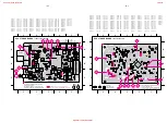
Circuit Diagram AF7 Board

6V

6V

6V

4,1V

8,3V

4,2V

4,1V

4,2V

4,2V

4,1V

4,2V

8,5V

4,2V

4,1V

9,1V

12V

4,2V

4,1V

5V

0V

0V

0,6V

5V

6V

6V

0,6V

6V

0V

0V

0V

1,3V

3,4V

12V

12V

6V

6V

4,2V

4,2V

0,6V

0,6V

4,8V

9,3V

1,1V

0,6V

1,1V

9,3V

4,8

0,6V

To and from Tuner Board

To and from Microphone Board

To and from CDR Module

Bass ALC Circuit

Bass ALC Circuit

Incredible Surround Circuit

8-4

8-4

www.freeservicemanuals.info

2/4/2018

Digitized in Heiloo Netherlands

Summary of Contents for FW-R8/17

Page 1: ...onics B V Eindhoven The Netherlands All rights reserved No part of this publication may be reproduced stored in a retrieval system or transmitted in any form or by any means electronic mechanical photocopying or otherwise without the prior permission of Philips SERVICING For servicing FW R8 the set can be divided into two parts 1 Except for the CD R W module the set has to be repaired on component...

Page 2: ...ds DESIGN FRONT BOARD LED BOARD FRONT BOARD CDC KEY BOARD M A I N S B O A R D TUNERBOARD AF7BOARD HEADPHONEBOARD MIC BOARD DIG SWITCH BOARD Location of PCB R8 2000 02 14 www freeservicemanuals info 2 4 2018 Digitized in Heiloo Netherlands ...

Page 3: ...ine 500mV 2dB Microphone 2 5mV 2dB at 1kHz CDC unit Frequency response within 20Hz 20kHz at 3dB Signal Noise ratio 94dB A weighted Distortion at 1kHz 0dB 90dB Channel unbalance 0 3dB Channel crosstalk at 1kHz 60dB De emphasis 0 or 15 50 µS Laser Output power 500µW Wave length 780nm 20nm CDR unit CD Playback Frequency response within 20Hz 20kHz at 3dB Signal Noise ratio 90dB A weighted Distortion a...

Page 4: ...Ω Bandpass 250Hz 15kHz e g 7122 707 48001 LF Voltmeter e g PM2534 DUT S N and distortion meter e g Sound Technology ST1700B Frame aerial e g 7122 707 89001 Tuner AM MW LW To avoid atmospheric interference all AM measurements have to be carried out in a Faraday s cage RF Generator e g PM5326 Ri 50Ω Low pass filter 22kHz L R LEVEL METER e g Sennheiser UPM550 with FF filter S N and distortion meter e...

Page 5: ...14 16 17 53 48 33 32 50 31 52 30 54 64 52 50 27 26 Remote control key Standby CD1 CD2 CD3 CDR Tuner Aux 1 ABC 2 DEF 3 GHI 4 JKL 5 MN 6 OPQ 7 RST 8 UVW 9 XYZ 0 Space YES NO EDIT TEXT PROGRAM PROGRAM TUNER MODE MUTE System Code 17 20 21 26 20 20 20 26 17 21 17 20 21 26 17 20 21 26 17 20 21 26 17 20 21 26 17 20 21 26 17 20 21 26 17 20 21 26 17 20 21 26 17 20 21 26 17 20 21 26 17 20 21 26 17 20 21 26 ...

Page 6: ...tion control Rotary control í JOG CONTROL ë CDC CDR selects the previous next track TUNER selects the previous next preset tuner station Keys to press YES confirms a selection á SEARCH CDC CDR searches forward reviews the tracks in a program controls the cursor in different menus TUNER tunes to a higher radio frequency É PLAY PAUSE starts and interrupts playback recording PROG opens closes the pro...

Page 7: ...300 Ω AM AE RIA L Antenna connections Speaker connections Power English INSTALLATION 9 AUX IN L R It is possible to use an additional appliance e g tape recorder TV or VCR with the unit 1 Insert the red plug of a cinch cable to the red jack AUX IN R and insert the white plug to the white jack AUX IN L 2 Connect the other end of the cinch cable to the audio outputs of the additional appliance 3 Pre...

Page 8: ... or CDRW CD R 1 2 3 disc tray 1 2 or 3 is selected and loaded with an unfinalized CDR CD RW 1 2 3 disc tray 1 2 or 3 is selected and loaded with an unfinalized CDRW CD Recorder COMPILE CDC current program is being recorded with high speed dubbing and auto finalize FM TUNER FM station is being recorded CD CD current disc is being recorded with high speed dubbing and auto finalize AUX material from ...

Page 9: ...mote control again Playing a CD RW Loading the CD changer CD recorder Switching on switching to standby CD CHANGE OPEN CLOSE DISPLAY CDR iR SENS OR TUNER DIGITAL ANALOG AUX CD TEXT CLOC K TIM ER OPEN CLOS E MIC MIC LEVEL CD TEX T EDITING STANDBY ON CD 1 CD 2 CD 3 REC TYPE EDIT COMPIL E CD FINALIZE ERASE CD CD RECORD FW R8 CD RECORDAB LE MINI HIFI SYSTEM CD RECO RDER CD REWRITABLE COMPATIBLE 3 CD C...

Page 10: ... on the remote control y PROG starts blinking and Program is displayed 4 If either CD 1 CD 2 or CD 3 is selected Rotate í JOG CONTROL ë to select either y CD1 or 2 3 All All tracks of CD 1 or 2 3 will be programmed y CD1 or 2 3 and track number The track number of CD 1 or 2 3 will be programmed If CDR is selected Rotate í JOG CONTROL ë press the numerical keys on the remote control for 2 digit num...

Page 11: ...disc is a simple procedure necessary to play a recorded CDR on a standard CD player or play a recorded CDRW on a CDRW compatible CD player and CD recorder Basic information English INTERNAL RECORDING 17 For internal recordings you can record from the internal CD changer or tuner You can choose from the following recording modes High speed recording and automatic finalizing Fast and easy Record and...

Page 12: ...g press Ç STOP on the unit DO NOT FORGET TO FINALIZE Finalizing a CDR W disc is a simple procedure necessary to play a recorded CDR on a standard CD player or play a recorded CDRW on a CDRW compatible CD player and CD recorder Normal recording and listening High speed recording English DISPLAY CDR iR SENS OR TUNE R DIGITAL ANALOG AUX CD TEXT CLOC K TIM OPEN CLO SE MIC MIC LEVEL CD TE XT EDITIN G S...

Page 13: ...g is displayed if the analog input is selected 3 Press REC TYPE on the unit to enter the recording menu 4 Rotate í JOG CONTROL ë to select the type of recording y AUX Manual for manual start of recording 5 Press YES to confirm your selection y Wait is displayed y Record AUX and the remaining recording time of the CDR W are displayed 6 Start playback on the external source in order to set the optim...

Page 14: ... CD CD RECO RD UN FINALIZING ERASING 23 If you want to record or erase on from a finalized CDRW you have to unfinalize it first Notes Unfinalizing will take approximately 2 minutes After unfinalizing of the CDRW CD changes to CDRW on the display When unfinalizing a CDRW with CD text on it available this text will be transferred to the CD recorder memory In case the memory is full you have to erase...

Page 15: ...rasing text 1 Press EDIT TEXT to enter the text edit menu y CD TEXT EDIT is blinking Text Edit is displayed 2 Rotate í JOG CONTROL ë to select the text erase menu y Text Erase is displayed 3 Press YES to confirm 4 Rotate í JOG CONTROL ë to select one of the following y All Text All text of the selected disc is chosen to be erased in one step y Album Artist CD artist s name is chosen to be erased y...

Page 16: ...anual programming 1 Follow steps 1 and 2 of Tuning to radio stations 2 Keep PROG PROGRAM on the remote control pressed for less than 2 seconds y PROG and the current preset number in the music calendar start flashing 3 Press à SEARCH or á SEARCH à or á on the remote control to tune to the desired radio station To allocate the radio station to another preset number rotate í JOG CONTROL ë pressí or ...

Page 17: ...dly to switch the alarm and or record timer on or off y ALARM is shown and Alarm ON is displayed when the alarm timer is on y REC is shown and REC Timer ON is displayed when the record timer is on y ALARM and REC are shown REC Alarm ON is displayed when the alarm and record timer are on y ALARM and REC go off REC AlarmOFF is displayed when the alarm and record timer are off You can set a certain p...

Page 18: ...No digital audio disc is inserted Insert a digital audio disc marked with Digital Use Audio CD indication Audio and the special logo Disc Recover indication Power loss Wait a few minutes The disc is being repaired Disc Error indication Disc Recover was not able The disc can still be played but not recorded to repair the disc or finalized further Check Input indication Wrong input is chosen Select ...

Page 19: ...cified be used Safety components are marked by the symbol i Le norme di sicurezza estigono che l apparecchio venga rimesso nelle condizioni originali e che siano utilizzati i pezzi di ricambiago identici a quelli specificati Componenty di sicurezza sono marcati con ñ Veiligheidsbepalingen vereisen dat het apparaat in zijn oorspronkeliijke toestand wordt teruggebracht en dat onderdelen identiek aan...

Page 20: ...ity test disc SBC444 4822 397 30245 Test disc 5 disc without errors Test disc 5A disc with dropout errors black spots and fingerprints SBC 426 426A 4822 397 30096 Burn in test disc 65 min 1kHz signal at 30dB level without pause 4822 397 30155 3 2 Service Tools Handling Chip Components www freeservicemanuals info 2 4 2018 Digitized in Heiloo Netherlands ...

Page 21: ...XX VXX S NTC XX N Y NTC TEST Display shows XX value in C Source AUX AUX button pressed STOP button pressed N Y N Y QUARTZ TEST Display shows 2048Hz can be measured on pin 9 of µP N Y SEARCH 5 button pressed SEARCH 5 button pressed Tact frequency µP divided 32kHz 32K Display shows 1465Hz can be measured on pin 9 of µP STOP button pressed N Y Tact frequency µP divided 12MHz 12M NEW N Y EEPROM CLEAR ...

Page 22: ...t MODULE INFORMATION MAIN BOARD DIAGNOSTIC CDR LOADER TEST DRAM TEST 7702 Display shows DTST1 CHECKSUM TEST 7703 Display shows DTST2 ERASE TEST 7208 Display shows DTST3 ADC DAC TEST 7406 Display shows DTST4 COMMUNICATION TEST DSA BUS Display shows DTST5 Display shows DERR n n number of failed test Display shows next error FFWD 6 button pressed N Y FFWD 6 button pressed Y FFWD 6 button pressed Y FF...

Page 23: ...A_OUT_LEFT SHIELD RIGHT 12V 12V PH TOP ENTRY PH SIDE ENTRY XH SIDE ENTRY 1 1 1 1 1 1 1 0041 1 1 21 1521 1537 1533 26 1528 8351 280mm AWG 26 7p 0012 0011 1351 1354 8004 140mm 1167 1142 1166 8003 400mm AWG 26 3p FFC 26 6p 1522 1 1 1 1 1 1 1 1 1 1 1 1 1 23 99 1 1 1 1 1 1 1 1 1 F2 F1 SW_INFO CD_SH_STR D_GND CD_SH_CLK SICL CD_SH_DATA SILD D_GND SRDT DQSY UP_CLK D_GND D_GND D_GND D_GND MIC_DET MIC_DET M...

Page 24: ...ER LEVEL GAIN AUX CDR99 3CDC TU 2 dB 0 dB 0 dB 0 dB ALC MIC 1 mV TUNER Nom 110 mV 3CDC99 DS Nom 1000 mV CDR99 Nom 1000 mV CDR99 Nom 500 mV Headphone out 0 dB 2800 mV LINE OUT Nom 500 mV Sectrum analyzer Nom 4000 mV DIGITAL IN Nom 500mVpp 3CDC99 Dig out Nom 500mVpp CDR99 Digital in Nom 2000mVpp Digital out 500mVpp 75Ω CDR99 Dig out Nom 500mVpp 2200mV 800 mV x100 x5 x5 AF 7 Board for details see Cha...

Page 25: ...7 2262 1174 7145 5130 5 1 3350 16 1 8 9 16 1 8 9 7142 9403 9404 9401 1160 1163 1 1 1 2 1162 4 3 3 6 4 3 1 5 2 4 6 9402 1164 CDR Mini Digital switch Board Copperside view stage 4 2000 03 08 1160 B2 1162 B1 1163 B2 1164 A2 2220 B2 2221 A1 2222 B2 2225 B2 2226 A2 2227 A2 2228 B1 2230 C1 2231 C2 2232 A1 2233 B1 2234 B1 2235 A1 2236 C2 3350 C2 3351 B1 3353 B2 3354 A1 3355 B2 3356 A1 3357 B2 3358 B1 335...

Page 26: ...DISPLAY BUS TUNER BUS CD TEXT BUS CD Swinfo 7108 MICROPROCESSOR TMP88CU77ZF 0043 1102 1 CD ShSTR CD ShCLK CD SICL CD ShDATA CD SILD TU CE TU Data TU CLK RDS RDS STEREO F2 F1 30V 5V6 0042 1 1 CD TxtIN CD TxtDQSV CD TxtCLK 1104 1 1105 I 2 CW_DATA I 2 CW_CLK CWReqKbe CWReset AM PM TIME TRACK PRESET STEP TOTAL TRACK TIME CD TEXT EDIT TRACK TUNER TUNER REC PROG ALARM SLEEP REPEAT SHUFFLE DISC TRACK ALL...

Page 27: ...8 3368 F7 5130 E8 5 6 DIGI_IO_SW1 DIGI_IO_SW0 DIGI_IO_SW0 to CDR DIG OUT EBU IN EBU_OUT SHIELD 3 4 5 SXXB EH A 1163 1 2 3 4 DIG FE ST VK N 1160 1 2 2230 100n ANA ANA 100K 3366 7140 E 74LVU04D 11 10 5VA DIG 3363 270R 2 5VIC DIG DIG 3361 470R 1162 B YKC21 3421 5 4 3 2231 100n 2225 100n DIG 3364 100R DIG DIG ANA DIG DIG 3 4 6 3367 82R ANA 5130 6RG 1 2 2 5VIC 220R 3359 EH S 1 2 3 2228 100n 1164 1n 223...

Page 28: ... C2 3176 A3 3177 B3 3178 A3 3179 B4 3180 A2 3181 A3 3182 B6 3183 B6 3184 B6 3185 C4 3186 A3 3187 A2 3188 B2 3189 B2 3190 B3 3191 B3 3192 B3 3193 B3 3194 B3 3195 B3 3196 B3 3197 B3 3198 B3 3199 B3 3200 A2 3201 A3 3202 A3 3203 B3 3204 B3 3205 B3 3206 B3 3207 B3 3208 B3 3209 B3 3210 B3 3211 B3 3212 B3 3213 B3 3214 C4 3215 C4 3216 C4 3217 C3 3218 C4 3219 C4 3220 B6 3221 B1 3222 C1 3223 C1 3224 C3 3225...

Page 29: ...127 15p 3169 220R BC847B 7103 2200 100n 1K 3196 6109 1N4148 220R 3131 1K 3205 6202 0403 3153 1K 1K 3225 220R 3133 220R 3111 6106 1K 0402 3112 220R 3227 D 5110 2u2 2124 10p 2199 10n 470p 2114 shield2 3189 470R 1n D 2195 47u 3162 220R D 2158 6206 270R 3146 10u 2156 D 7106 BC847B 1K 3213 G11 G8 G5 G2 G10 G7 G4 G1 CDSwInfo 30V 5V6 F2 F1 AmNTC SA_IN 1K 3156 P32 P33 P26 P30 P22 P25 P18 P19 P12 P13 P10 P...

Page 30: ... G4 F492 G4 F493 G4 F494 H4 F495 H4 F496 H4 F497 H4 F498 H4 F499 H4 F500 H4 2K7 0043 1 2 3 1 2 3 47R 3293 3267 D DIPMATE 10K 1n 2175 100n 2182 3240 220R 3251 KEY 5 Y5 Y6 2 4 Y7 3 Z D 6 E_ 8 11 10 9 16 7 VEE 13 Y0 14 Y1 15 Y2 12 Y3 1 Y4 3273 100n 2185 HEF4051BT 7122 D D 150R 2165 100p 1N4148 6121 6123 1N4148 3271 150K 3286 680K 3288 220K 3281 1K 10K 3241 KEY 82p 2170 SCOUT 15 T57 10 TEST 5 VDDA 12 ...

Page 31: ...103 A1 6104 A1 6105 A1 6106 A7 6107 A7 6108 C5 6109 D7 6110 C4 6120 A7 6121 A6 6122 A6 6123 A6 6124 A7 7112 A7 9001 A1 9002 A3 9003 A3 9004 A4 9006 A4 9007 A4 9009 A5 9010 A5 9012 A6 9013 A6 9014 A7 9015 A6 9016 A6 9017 A6 9018 B6 9019 B6 9020 B6 9021 B6 9022 B6 9023 A7 9024 A7 9026 A7 9027 A7 9028 A7 9029 B7 9030 B7 9031 B7 9032 B7 9033 C6 9034 C6 9035 C6 9036 C6 9037 B6 9038 B6 9039 B6 9040 B6 9...

Page 32: ...03 B4 3304 C8 3305 C8 3306 C8 3307 B4 3312 B3 3313 C3 3314 C3 3315 C3 3316 B2 3317 C3 3318 B4 3319 B4 3320 C6 3321 C5 3322 C6 3323 C6 3324 C7 3325 B8 3326 B6 3327 C8 3328 B8 3329 A8 3330 B6 3331 C9 3332 B8 3333 A6 3334 C8 3335 A7 3337 A6 3338 B9 3339 A7 3340 A9 3341 A7 3342 A4 3343 A2 3344 A2 3345 A3 3501 A3 3502 A3 3503 A3 3504 A3 3505 A7 3506 A7 3507 A7 3508 A7 4102 C8 4103 C8 4104 C9 4105 A7 41...

Page 33: ...M16 6143 E16 6150 L18 6151 K18 6152 F17 6153 E17 6154 D17 6155 K18 6156 M18 6157 E17 7130 C13 7131 F16 7132 I13 F400 C4 F401 D4 F402 D4 F403 D4 F404 D4 F405 E4 F406 E4 F407 E4 F408 E4 F409 F4 F410 F4 Play Pause Next F411 F4 F412 F4 F413 C4 F414 A4 F415 B4 F416 B4 F417 C4 F418 L15 F419 L16 F420 M15 F421 M16 F550 D16 F551 D15 F552 E16 F553 E16 F554 G16 F555 J16 F556 K16 F557 K16 F558 K16 F559 L16 2 ...

Page 34: ...1 6161 1N4148 12A 2241 470u 2255 10u 2243 10u 1n 2253 2257 1n 2K7 3379 7152 BC857B 10n 2242 12A 4K7 3393 3383 20K 2 1 3 12A 2K2 3387 100u 2258 Microphone Board 0V 0V 0 7V 0 1V 3 9V 4 6V 1 3V 7 3V 0 3V 0V 0V DC Voltages measured with connected microphone 9 4V 0 9V 0V 0V 1 9V 5 9V V EVM V CDR Mini Microphone Board Copperside view stage 4 2000 03 07 3383 1 1 2 6 9 4 7 3 3 6161 6162 1166 1 3 1 4 1167 ...

Page 35: ...22 126 10326 180pF 5 2122 4822 126 10326 180pF 5 2124 5322 122 32448 10pF 5 50V 2125 5322 122 32448 10pF 5 50V CAPACITORS 2126 5322 122 32448 10pF 5 50V 2127 4822 126 13486 15pF 2 63V 2128 4822 126 13486 15pF 2 63V 2134 4822 124 12245 220µF 20 16V 2135 4822 126 10326 180pF 5 2136 4822 126 10326 180pF 5 2137 4822 126 10326 180pF 5 2138 4822 126 10326 180pF 5 2139 4822 126 10326 180pF 5 2140 4822 12...

Page 36: ...02 1kΩ 5 0 2W 3096 4822 051 20471 470Ω 5 0 1W 3097 4822 051 20471 470Ω 5 0 1W 3098 4822 051 20471 470Ω 5 0 1W 3099 4822 051 20471 470Ω 5 0 1W 3101 4822 051 20472 4 7kΩ 5 0 1W 3102 4822 117 11149 82kΩ 1 0 1W 3103 4822 117 11149 82kΩ 1 0 1W 3104 4822 117 11503 220Ω 5 0 1W 3105 4822 117 11503 220Ω 5 0 1W 3106 4822 117 11503 220Ω 5 0 1W 3107 4822 117 11503 220Ω 5 0 1W 3108 4822 117 11503 220Ω 5 0 1W 3...

Page 37: ...00Ω 5 0 1W 3215 4822 051 20478 4 7Ω 5 0 1W RESISTORS 3216 4822 051 20478 4 7Ω 5 0 1W 3217 4822 051 20684 680kΩ 5 0 1W 3218 4822 051 20478 4 7Ω 5 0 1W 3219 4822 051 20478 4 7Ω 5 0 1W 3220 4822 051 20101 100Ω 5 0 1W 3221 4822 051 20101 100Ω 5 0 1W 3222 4822 117 10833 10kΩ 1 0 1W 3223 4822 117 10833 10kΩ 1 0 1W 3224 4822 051 20684 680kΩ 5 0 1W 3225 4822 051 10102 1kΩ 2 0 25W 3226 4822 117 10837 100kΩ...

Page 38: ...3345 4822 052 10478 4 7Ω 5 NFR RESISTORS 3350 4822 116 83883 470Ω 5 0 16W 3351 4822 117 10833 10kΩ 1 0 1W 3353 4822 117 11148 56kΩ 1 0 1W 3354 4822 051 20399 39Ω 5 0 1W 3356 4822 117 11449 2 2kΩ 1 0 1W 3357 4822 051 20683 68kΩ 5 0 1W 3358 4822 117 10833 10kΩ 1 0 1W 3359 4822 117 11503 220Ω 5 0 1W 3362 4822 051 20471 470Ω 5 0 1W 3364 4822 051 20101 100Ω 5 0 1W 3366 4822 117 10837 100kΩ 1 0 1W 3367 ...

Page 39: ...CHIP JUMPER 0805 4107 4822 051 20008 CHIP JUMPER 0805 4108 4822 051 20008 CHIP JUMPER 0805 4109 4822 051 20008 CHIP JUMPER 0805 4110 4822 051 20008 CHIP JUMPER 0805 4111 4822 051 20008 CHIP JUMPER 0805 4112 4822 051 20008 CHIP JUMPER 0805 RESISTORS 4201 4822 051 20008 CHIP JUMPER 0805 4203 4822 051 20008 CHIP JUMPER 0805 4204 4822 051 20008 CHIP JUMPER 0805 4205 4822 051 20008 CHIP JUMPER 0805 420...

Page 40: ...130 60511 BC847B 7154 4822 130 42804 BC817 25 7155 4822 130 60511 BC847B 7156 4822 130 60511 BC847B 7160 4822 130 60511 BC847B INTEGRATED CIRCUITS 7107 4822 209 15449 74HC4094D SHIFT REGISTER 7108 8203 303 90210 TMP88CU77ZF µP 7110 9322 131 04668 M24C01 EEPROM 7112 9322 137 14667 IR RECEIVER TSOP2836ZC1 7120 4822 209 17345 M62320FP I2C SHIFT REGISTER 7121 4822 209 31981 SAA6579T V1 RDS DECODER 712...

Page 41: ...F CONTENTS Adjustment table 7A 2 Blockdiagram 7A 3 Circuit Diagram 7A 4 Component Layout 7A 5 Electrical Partslist 7A 6 Tuner 95 3 Band RDS Tuner www freeservicemanuals info 2 4 2018 Digitized in Heiloo Netherlands ...
Page 42: ...l inside tuner 1110 450kHz f 10kHz as low as possible 6 3 1 7 7 A FM IF 0mV 3mV 98MHz 5107 FM 98MHz 1mV continuous wave 1 2 A min distortion 4 A 0mV 2mV 5114 450kHz continuous wave 2 C Repeat 50R 100nF C 5112 shortcircuit pin 21 of IC7108 to ground 1 If sensitivity of frequency counter is too low adjust to max channel separation input signal stereo left 90 9 adjust output on right channel to minim...

Page 43: ...FM Osc CHARGE PUMP 8 I Tune 24 Mono FM GND 3 4 RF GND 17 IF GND 26 Dig GND 42 RF GND 1 Ripple AM Osc MW LW SELECTION 6 PILOT Filter Fieldstrength 22 VCC2 TEA5762 FM FRONTEND 1102 A B B AGC 6 3 Fo Osc Out IF Out Ant1 7 1 GND 4 8 a F if F 10 7 MHz f0 fin fif FM MT MT 5 VT 75kHz 10 7MHz VC0 IF AM IF AM AM DET ANTI BIRDY FILTER 2 1 450kHz 450kHz 5111 5112 5114 450kHz 3 DATA ENABLE RDS 4 CLOCK 5 STEREO...

Page 44: ...61 1121 2147 2148 3140 3104 1103 5102 2106 6105a 2107 3131 3123 6105b 7104 2109 2108 7105 3109 3108 5123 2120 2123 5122 2122 2125 3134 5103 3137 7124 3169 3128 7122 7109 3197 3125 3130 3129 3163 7103 3186 3143 3144 3184 2127 7110 3167 2142 2144 6107 3146 3154 3155 2143 2130 3172 3124 3132 3181 3107 7101 3188 3150 5121 2161 3162 2160 3164 2162 3151 3177 1126 2151 5107 2152 1 1 2 2 3 3 4 4 5 5 6 6 7...

Page 45: ...3140 G8 3141 F9 3142 F10 3143 F8 3144 G9 3145 E9 3146 A10 3147 G9 3150 B11 3151 B10 3152 F9 3153 F9 3154 B10 3155 B10 3158 F11 3159 F11 3160 F11 3161 F11 3162 C9 3163 E8 3164 B11 3165 C8 3167 E8 3169 C5 3171 C11 3172 E7 3173 E7 3176 C9 3177 E7 3178 A8 3181 C8 3183 D7 3184 D7 3185 D7 3186 F8 3188 F11 3192 C8 3197 B7 5102 B4 5103 B5 5107 E10 5109 C7 5110 D9 5111 B8 5112 B9 5114 C8 5115 F9 5121 D9 51...

Page 46: ... 10008 CHIP JUMPER 1206 3132 4822 051 20008 CHIP JUMPER 0805 3134 4822 051 20223 22kΩ 5 0 1W 3137 4822 117 10833 10kΩ 1 0 1W RESISTORS 3140 4822 051 20331 330Ω 5 0 1W 3141 4822 117 11148 56kΩ 1 0 1W 3142 4822 100 11163 100kΩ TRIMPOT LIN 3143 4822 051 20223 22kΩ 5 0 1W 3144 4822 051 10102 1kΩ 2 0 25W 3145 4822 117 11449 2 2kΩ 1 0 1W 3146 4822 051 20479 47Ω 5 0 1W 3150 4822 051 20472 4 7kΩ 5 0 1W 31...

Page 47: ...F CONTENTS Adjustment table 7B 2 Blockdiagram 7B 3 Circuit Diagram 7B 4 Component Layout 7B 5 Electrical Partslist 7B 6 Tuner ECO 5 3 Band Tuner www freeservicemanuals info 2 4 2018 Digitized in Heiloo Netherlands ...
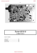
Page 48: ...A 5119 FM 10 7MHz 50mV continuous wave 2 F mod 1kHz f 22 5kHz 1 If sensitivity of frequency counter is too low adjust to max channel separation input signal stereo left 90 9 adjust output on right channel to minimum Repeat ECO5 discr coil 090797 TUNER ADJUSTMENT TABLE ECO5 FM MW and FM MW LW versions with AM frame aerial f 15kHz VRF 3mV C see remark 2 220R 100nF 36 IC 7101 220R 100nF 40 IC 7101 21...

Page 49: ...lexer Charge pump CONTROL AM FRAME AERIAL Reference Oscillator 1126 1 4 1 4 6 1 stereo 27 28 29 clock data enable clock data enable Version P1 P0 MW LW 31 30 programmable output ports AM RF AM Osc 3 5 1121 VLoop VLoop VLoop VLoop VLoop 2 6 5 43 1103 B C 450kHz 450kHz 450kHz 20 75kHz VStabA VStabB VStabB VStabA VStabB 10 7 MHz 10 7 MHz 35 9 Vcc Vdd Vcc1 7 23 VStabA VStabB 38 34 22 Vcc2 8 ECO5 sys 2...

Page 50: ...A 4 9117 L10 9101 C 6 9100 B 4 7124 M13 7125 I16 7122 M 9 7119 B13 7111 F18 7109 M 7 7105 F 2 7104 E 3 7103 I 9 7102 D 8 7101 G11 4 5 1 6 7 8 9 10 11 12 13 14 15 2 16 17 18 19 20 21 3 K J N I H G F E D C B A M L K J N I H G F E D C B A M L 4 5 1 6 7 8 9 10 11 12 13 14 15 2 16 17 18 19 20 21 3 HN1V02H Chip jumper 8 7 6 5 4 3 2 1 6105 z_TEA5759 to from COMBI BOARD Source Selector part to from CONTRO...

Page 51: ...132 4111 6105 6110 3108 3133 4101 4102 4155 2108 2109 2113 2124 7108 4109 4110 4156 3112 3114 3116 3117 3121 2114 2117 3109 3177 3113 4159 3155 3156 3175 2143 2163 3181 2105 6101 9119 A B C A B C 5 4 3 2 1 5 4 3 2 1 3148 3146 3178 3179 4160 4161 7111 7125 4158 3144 4162 4163 2126 2165 2156 3119 2111 4104 2161 2127 7121 3127 2141 2142 2164 2139 2168 3140 7106 3125 7109 3111 3123 3115 3180 5 1 C F 4...

Page 52: ... 20008 CHIP JUMPER 0805 3132 4822 116 52195 47Ω 5 0 5W 3134 4822 051 20223 22kΩ 5 0 1W 3141 4822 117 11148 56kΩ 1 0 1W RESISTORS 3142 4822 100 12159 TRIMPOT 100kΩ 3145 4822 117 11449 2 2kΩ 1 0 1W 3146 4822 051 20229 22Ω 5 0 1W 3152 4822 116 83883 470Ω 5 0 16W 3153 4822 051 20471 470Ω 5 0 1W 3154 4822 116 83868 150Ω 5 0 5W 3155 4822 051 20471 470Ω 5 0 1W 3156 4822 117 10837 100kΩ 1 0 1W 3158 4822 1...

Page 53: ...93 A3 2694 A3 2695 A2 5523 A3 5531 B2 5532 B2 9641 A3 1 2 3 4 5 6 100n 2694 22n 2692 2u2 5531 2691 100n 5532 2u2 6 2u2 TC38 1543 9 8 7 1 2 3 4 5 GNDa Lhp L R Rhp DPL_SW FE BT VK N 1542 Provision Note Some values may varies see respective parts list for correct value 8239 210 85580 8 2 3 9 2 1 0 8 5 5 8 0 4716 4715 2695 2691 2694 2693 2692 Headphone Board Componentside view Copperside view www free...

Page 54: ...UTE LO SA_IN NTC NTC PW_DN I 2 C_DATA I 2 C_CLK 5V6 30V F1 F2 AB AMP_ON 12A L R 12M 5V6 MUTE_SW p L R AF7 BOARD Headphone Board CDR Module for details see separate blockdiagram Chapter 11 TUNER for details see separate blockdiagram Chapter 7 3CDC Module for details see separate blockdiagram Chapter 10 Front Board for details see separate blockdiagram Chapter 6 Front Board for details see separate ...

Page 55: ... 3610 F8 3611 F8 3612 F7 3613 F7 3614 F7 3615 F7 3616 F7 3617 E7 3618 F7 3619 E7 3620 F7 3621 E7 3622 F7 3623 F7 3624 F7 3625 E6 3626 F6 3627 F6 3628 F6 3629 E6 3631 E3 3633 F4 3634 F4 3635 E3 3636 F3 3637 E3 3638 F3 3639 E4 3640 F4 3642 F3 3643 F3 3645 E3 3646 F3 3647 F3 3648 F3 3649 B5 3650 B5 3651 B5 3652 B5 3653 E2 3656 B8 3657 B8 3658 B8 3659 B8 3660 B8 3662 F3 3663 F3 3665 B6 3666 B7 3667 D6...

Page 56: ... BASS_OUT_L 27 BASS_OUT_R 38 CLK 39 CREF 19 CSM 37 DATA 36 DGND 13 DIFF_GND_L 5 DIFF_GND_R 14 DIFF_L 6 DIFF_R 41 DVDD 34 FRONT_L 33 TDA7437 7511 40 ADDR 43 AGND 42 4K7 3642 100n 2671 1n 2613 3527 1K 8K2 3621 2598 220p 3622 8K2 3616 5K6 a 4517 a 4518 47K BC847B 7534 1K5 3546 150K 3587 a 3643 4K7 3565 4K7 a 12M 2531 22n 2539 100p IS 820R 3629 1N4148 6515 3563 2K7 12A a 47K 3623 3605 220K 3553 330K 3...

Page 57: ...ont Board To Front Board To Power amplifier To Headphone Board Open if Headphone is connected To Digital Switching Board To and from CD Board MUTE CIRCUIT Incredible Surround Circuit 8 5 8 5 0021 E1 0026 H1 0027 D21 0030 H20 1521 A1 1525 C1 1526 H1 1527 F21 1528 C21 1533 G22 1535 G21 1537 H22 1538 G22 2216 F15 2355 D17 2511 E2 2512 E2 2513 D3 2514 F3 2515 D4 2516 F4 2517 F11 2519 E4 2520 F4 2521 E...

Page 58: ... C8 2876 C2 3513 D2 3514 D2 3533 D6 3539 C6 3558 E2 3576 F5 3579 E7 3593 F5 3599 D3 3607 F3 3608 F3 3632 F6 3641 F4 3655 B3 3661 B6 3681 F2 3685 C5 3695 B1 3697 C2 3698 C3 3699 C4 3737 B8 3739 B6 3745 B8 3746 C8 3752 C7 3772 B9 3773 B9 5511 F5 5611 B1 5612 B1 5711 B9 5712 C8 5714 B9 6511 B7 6512 E2 6513 A5 6514 A4 6515 F2 6516 F2 6517 B5 6531 B4 6711 B9 7525 E2 7552 C2 9511 C6 9512 B8 9513 A5 9514...

Page 59: ...4 22nF 10 63V 2655 4822 124 40769 4 7µF 20 100V 2661 4822 124 21913 1µF 20 63V 2662 5322 122 31647 1nF 10 63V 2663 5322 122 32448 10pF 5 50V CAPACITORS 2664 4822 124 21913 1µF 20 63V 2665 4822 124 40248 10µF 20 63V 2666 4822 124 40207 100µF 20 25V 2668 5322 122 34099 470pF 10 63V 2669 4822 126 13838 100nF 10 50V 2670 4822 126 13838 100nF 10 50V 2671 4822 126 13838 100nF 10 50V 2672 4822 126 13838 ...

Page 60: ... CHIP JUMPER 0805 4548 4822 051 20008 CHIP JUMPER 0805 4549 4822 051 20008 CHIP JUMPER 0805 4550 4822 051 20008 CHIP JUMPER 0805 4551 4822 051 20008 CHIP JUMPER 0805 4552 4822 051 20008 CHIP JUMPER 0805 4553 4822 051 20008 CHIP JUMPER 0805 4554 4822 051 20008 CHIP JUMPER 0805 4555 4822 051 20008 CHIP JUMPER 0805 4556 4822 051 20008 CHIP JUMPER 0805 4557 4822 051 20008 CHIP JUMPER 0805 RESISTORS 45...

Page 61: ...5 Component layout Mains part 9 6 Component layout Supply part and L R Amplifier part 9 6 Circuit diagram L R Amplifier part 9 7 Circuit diagram CDR Supply part 9 8 Component layout CDR Supply part 9 9 Exploded view 9 10 Partslist 9 11ff POWER 5 VA Module 70 100W Version Stage 6 Technical remarks www freeservicemanuals info 2 4 2018 Digitized in Heiloo Netherlands ...

Page 62: ... pin 10 Mains Transformer 21 Mains transformer 4 for 21 only 8902 Transformer Pin 5 Transformer Pin 3 Pin 6 Pin 7 Pin 8 REL MFD V GND Pin 4 2 8901 1909 1910 1901 Mains socket 27 1 1 1 primary Mains part Interconnection Board Interconnection Board 7 CDR ON GND GND 12M GNDD 5 6V AMP ON 12M GNDA 12A RIN GND LIN PD AB STBY 30V F2 F1 CDR ON NTC REL MFD V GND VL VH VH VL GNDL GND GNDR CDR ON GND GND 12M...

Page 63: ...52 7254 7260 7263 6281 7281 6295 6906 6905 5903 7280 V 7260 7253 7255 STANDBY STANDBY REL PD Stand by Transformer Mains Transformer with interconnection boards Stand by Relais Mains socket 1911 8 Matrix Surround Amp on off mute SOAR Prot L R AMP OFF CONTROL LEFT RIGHT AMPLIFIER SUPPLY PART 7329 DC MFD MFD Mains Failure Detection BLOCK DIAGRAM 70 100W VERSION www freeservicemanuals info 2 4 2018 Di...

Page 64: ...2368 C 4 2369 C 4 3248 A11 3249 A11 3250 A11 3251 D13 3252 D12 3253 A13 3254 B 7 3255 E13 3256 B13 3257 E12 3258 E12 3259 A12 3260 C12 3261 C11 3262 C12 3263 B12 3265 B12 3266 A 8 3267 A 8 3268 A10 3269 B10 3270 C12 3271 D 7 3272 E13 3273 B 8 3274 E 8 3275 D 8 3278 D13 3279 E12 3280 A13 3281 C12 3282 C 7 3283 D11 3284 D11 3285 B 9 3286 B10 3287 B11 3288 B10 3289 B10 3290 E 8 3295 D 7 3296 E 8 3298...

Page 65: ...5392 6902 1N4003 6901 1N4003 6290 BZX79C5V6 6265 BZX79B11V 6264 BZX79C6V8 6298 BZX79C8V2 6293 BZX79 3V3 6302 BZX79C5V6 6284 BZX79C8V2 6908 0010 1 2 3 4 6271 1N4148 6270 1N4148 1N4002 6281 6267 1N4148 6299 1N4148 6296 1N4148 6295 1N4148 6297 1N4148 6292 1N4148 1N5392 6252 1N4003 6253 1N5392 6294 6301 1N4148 6283 1N4148 1N4003 6909 1N4003 6910 1N4148 6911 1N4148 6912 1N4148 6905 1N4148 6906 1N4003 6...

Page 66: ...80 3256 3255 1268 3272 6263 2264 3278 6260 6261 6262 9 2263 9274 3317 1258 7263 3253 1 2 3 4 5 6 7 8 9 10 11 12 13 1 2 3 4 5 6 7 8 9 10 11 12 13 E D C B A 3 C 2 8 D 9 9 B13 10 B10 11 D 8 14 D 9 16 A 4 1258 A13 1261 C 6 1262 A12 1263 A 7 1264 A10 1265 C 9 1268 D13 1280 C 7 1290 E11 1291 C 9 1321 D 6 1322 B 6 1323 B 6 1324 B 6 1325 B 2 1326 B 1 1327 A 4 1328 E 4 2251 D10 2252 E10 2253 D10 2254 D 9 2...

Page 67: ...343 1k 3338 3336 3335 1k 3337 47k 3370 47k 3369 82k 3367 82k 3368 3329 3330 56k 3327 56k 3328 1k2 3326 1k2 3325 10k 3346 100R 3348 33k 3347 56k 3332 56k 3331 3366 3365 9321 9322 100n 2354 100n 2353 4n7 2356 4n7 2355 2329 220p 2327 2330 220p 2328 3n3 2325 3n3 2326 100n 63V 2350 100n 63V 2351 22n 2365 2 2u 2343 10u 100V 2349 22u 50V 2334 22u 50V 2333 2u2 50V 2324 2u2 50V 2323 1000u 10V 2352 10u 100V...

Page 68: ...62 22K 1K 2356 100n 3359 3360 100u 2360 6359 1N4148 3363 560R 6362 BZX79 C4V7 2359 47u 7357 BC327 40 3364 470R GND_P 1 2 GND_P 7350 BC557C GND_D 7355 BC337 40 BZX79 F3V9 GND_P 47u 100R 3351 6354 2352 6m8 2351 1N5392 6353 470u 2355 3358 150R 1N4003 6357 1N4003 GND_P 2354 470u 6358 GND_P GND_P 2363 GND_P GND_P 3374 39K 100u 1350 T2A5 10K 3361 100K 6361 1N4003 6365 BZX79 C3V9 3371 6360 BC327 25 7358 ...

Page 69: ...64 E1 6365 C1 7350 D2 7351 C5 7352 C3 7353 C3 7354 D3 7355 B5 7356 D5 7357 D4 7358 C1 7359 E2 7360 E3 9350 C6 9351 C6 9352 C4 9353 B3 9354 D3 9355 E4 9356 C7 9357 C6 1350 1355 1353 3358 3376 2360 2357 3371 2359 7356 2355 9355 2358 3370 6355 9354 6356 3369 7359 2350 3365 2351 2363 1354 3359 2362 3372 3366 3350 6354 6364 3352 3353 3361 3373 7360 7354 7353 6359 7352 9353 012 9352 6363 6362 3364 3363 ...

Page 70: ...x10 TORX 2x SCREW 3x16 TORX 2x AIRFLOW 501 502 507 511 509 506 4x SCREW 3x10 TORX 2x SCREW 3x16 TORX 2x SCREW 2 9x13 TORX 3x CDR SUPPLY PART 1241 508 513 512 EXPLODED VIEW Power5VA Module www freeservicemanuals info 2 4 2018 Digitized in Heiloo Netherlands ...

Page 71: ...100V 2330 5322 122 32818 2 2nF 10 100V 2331 5322 122 32261 4 7nF 10 100V CAPACITORS 2333 4822 124 81151 22µF 20 50V 2334 4822 124 81151 22µF 20 50V 2337 4822 122 10465 4 7pF 10 50V 2338 4822 122 10465 4 7pF 10 50V 2341 4822 126 11585 22nF 20 50V 2342 4822 126 11585 22nF 20 50V 2343 4822 124 22652 2 2µF 20 50V 2344 4822 124 40764 22µF 20 100V 2345 4822 124 40764 22µF 20 100V 2348 4822 124 81043 10µ...

Page 72: ...72 220Ω 5 0 5W 3392 4822 116 83872 220Ω 5 0 5W 3901 4822 053 21106 10MΩ 5 0 5W 3902 4822 050 11002 1kΩ 5 0 2W 3903 4822 050 11002 1kΩ 5 0 2W 3904 4822 116 52244 15kΩ 5 0 5W 3904 4822 116 52283 4 7kΩ 5 0 5W RESISTORS 3905 4822 116 52256 2 2kΩ 5 0 16W 3906 4822 050 21003 10kΩ 2 0 25W 3908 4822 053 10121 120Ω 5 1W 3908 4822 053 10471 470Ω 5 1W 3920 4822 052 10108 1Ω 5 0 33W COILS 5321 4822 157 70599 ...

Page 73: ... 5W 3357 4822 116 52206 120Ω 5 0 5W 3358 4822 053 11151 150Ω 5 2W 3359 4822 050 21101 110Ω 1 0 6W 3360 4822 050 11002 1kΩ 5 0 2W 3361 4822 050 21003 10kΩ 2 0 25W 3362 4822 116 52257 22kΩ 5 0 5W 3363 4822 116 52226 560Ω 5 0 5W 3364 4822 116 83883 470Ω 5 0 16W 3365 4822 116 83872 220Ω 5 0 5W 3366 4822 052 10568 5 6Ω 5 0 33W 3369 4822 116 52226 560Ω 5 0 5W 3370 4822 116 52249 1 8kΩ 5 0 16W 3371 4822 ...

Page 74: ...arnings 10 6 Blockdiagram 10 7 Wiring 10 8 Circuit Diagram part1 10 9 Component Layout 10 10 Circuit Diagram part2 10 11 Exploded View 10 12 Mechanical Partslist 10 13 Electrical Partslist 10 15 3CDC99 DS Module 3 Disc Carousel Changer www freeservicemanuals info 2 4 2018 Digitized in Heiloo Netherlands ...

Page 75: ...r outwards B Unlock drawer with screwdriver C Lift drawer to demount from chassis Dismantling of Flex Plate D Lift plate to unlock pin from bottom plate E Move plate inwards to demount from bottom plate www freeservicemanuals info 2 4 2018 Digitized in Heiloo Netherlands ...
Page 76: ...ve support in upper position as shown in picture below A 5 Dismantle CD drive support pos 95 B 6 Replace CD drive pos 100 The wire tree of JST connector has to be desoldered and resoldered on the new CD drive again 10 3 Servicing Hints A B Mounting of Carousel 1 Turn gearwheel pos 42 of disc change mechanism by finger until CD drive is in play position 2 Mount carousel pos 115 so that disc is posi...

Page 77: ... grove Grease on top of rib Grease Grease on top of highest ring Grease on four rectangular surfaces Grease inside groves Grease on slide Grease on four profile groves CHASSIS DRAWER www freeservicemanuals info 2 4 2018 Digitized in Heiloo Netherlands ...
Page 78: ...ISC CHANGE MECHANISM Grease Grease Grease on first and last tooth Grease on first and last tooth Use only grease Polylub GLY 801 service codenumber 4822 390 10136 www freeservicemanuals info 2 4 2018 Digitized in Heiloo Netherlands ...
Page 79: ...serunit see below CHARGED CAPACITORS ON THE SERVO BOARD MAY DAMAGE THE CD DRIVE ELECTRONICS WHEN CONNECTING A NEW CD MECHANISM THAT S WHY BESIDES THE SAFETY MEASURES LIKE SWITCH OFF POWER SUPPLY ESD PROTECTION ADDITIONAL ACTIONS MUST BE TAKEN BY THE REPAIR TECHNICIAN WARNING fig 1 Attention The laser diode of this CD drive is protected against ESD by a solder joint which shortcircuits the laser di...

Page 80: ...OR DISC CD MECHANISM FOCUS MOTOR RADIAL MOTOR SLEDGE MOTOR MOTOR TURNTABLE PHOTODIODE HF AMPLIFIER LOADER CONTROL PCB EN1 DATA STB SHR_CL SICL SILD PORE 7878 MC78L05ACP 7875 7801 3 3V CD LEFT 7810 7877 CD RIGHT Laser Control HF AMPLIFIER TZA1024 TZA1025 55 54 56 38 13 18 20 21 23 2 1 5 3 27 29 26 28 10 12 14 13 SWITCH INFO 17 5 9 7 16 15 16 42 40 39 5 17 21 52 57 59 60 64 1 13 5V 2 4 5 7 V4 61 2 6...

Page 81: ...10 8 Wiring of CD Drive Pict 1 Pict 2 8005 www freeservicemanuals info 2 4 2018 Digitized in Heiloo Netherlands ...
Page 82: ...47p 2842 2n2 33R 470R 3853 47u 2839 2844 270p 3866 10K 3 3V 470R 3873 3848 3800 56K 100K 2869 47n 5V MON 4 PWRON 7 RFEQO 10 RFFB 9 RGADJ 14 VCC2 13 VCCL 2 TZA1024 7801 CDRW 11 CFIL 3 CMFB 8 DIN 5 EQSEL 12 6 GND LD 1 22K 3826 3728 10n 2859 1K 3825 4K7 22K 2807 330p 3709 3 3V 3846 33K 10V 3 3V 3806 10K 100R 3897 22K 3828 2892 4n7 180p 2855 470p 2802 3844 4K7 47u 3 3V 2837 2815 33n 1K 3824 4u7 2849 3...

Page 83: ...3730 B5 3731 C5 3760 B3 3761 B3 3762 B3 3763 C4 3764 C2 3766 B3 3768 J4 3769 J4 3800 D2 3801 D2 3802 D3 3803 D2 3805 D2 3806 D2 3807 D2 3808 D2 3809 D5 3811 D2 3812 G4 3814 D2 3815 D1 3816 E5 3817 E4 3819 B5 3820 E2 3821 E2 3822 E3 3823 F1 3824 F1 3825 G3 3826 E4 3827 E3 3828 F4 3831 C2 3832 A2 3833 F2 3834 F2 3835 H4 3837 E5 3838 D5 3839 E5 3840 E5 3841 E5 3842 E5 3843 G4 3844 G4 3845 E5 3846 G4 ...

Page 84: ... 13 14 15 16 GNDA 22u 2858 10K 470R 3893 10K 3714 3888 22u 2860 3 3V 22n 2875 470R 3706 4U7 5805 2830 10n 2872 47n 1K 3761 1 2 DIPMATE 1878 1 2 1876 DIPMATE 2863 220u 7878 47n 2876 3 3V GNDA 9 Os 10 STR 1 VDD 16 VSS 8 7873 CP 3 D 2 15 O0 4 5 O1 O2 6 O3 7 O4 14 13 O5 O6 12 O7 11 GNDA HEF4094BP 22u 3875 10K 2861 3872 3700 10K 1 EXCK GND 7 MCK 5 SBSO 2 SCLK SCLK 11 SCOR 3 SRDT SRDT 12 SW1 9 SW2 10 TE...

Page 85: ...8 96 98 96 108 106 107 105 23 123 24 21 54 60 25 115 22 100 95 6x 61 82 80 73 74 70 81 83 84 POS 60 48 39 35 38 45 43 50 51 42 52 44 53 40 41 47 46 26 POS 25 www freeservicemanuals info 2 4 2018 Digitized in Heiloo Netherlands ...

Page 86: ...PRING 0024 4822 492 11721 SPRING 0038 4822 502 12548 SCREW M2 6x3 5 0039 4822 502 12548 SCREW M2 6X3 5 0040 4822 463 11237 SLIDE 0041 4822 522 10509 CONTROL DISC 0042 4822 522 10492 GEAR WHEEL 0043 4822 528 10937 PULLEY 0044 4822 522 10493 IDLER WHEEL 0045 4822 358 10115 BELT 0046 4822 466 10735 ECCENTRIC GEAR WHEEL 0050 4822 532 12364 WASHER 0051 4822 532 12364 WASHER 0052 4822 532 12364 WASHER c...

Page 87: ...95 4822 404 10985 SUPPORT VAM 0096 4822 529 10387 RUBBER DAMPER CD DRIVE FRONT 0097 4822 529 10387 RUBBER DAMPER CD DRIVE FRONT 0100 9305 022 30201 VAM2202 01 0115 4822 466 10736 CAROUSEL 0117 4822 532 12365 BUSH DRAWER 0123 4822 402 11237 SWITCH BRACKET 0125 4822 401 11708 DISC CLAMP VAM DRIVE 3CDC 10 14 9 8 3 12 13 10 2 14 7 4 6 5 MECHANICAL PARTSLIST 3CDC 99 MODULE www freeservicemanuals info 2...

Page 88: ...0V 2862 4822 124 11912 220µF 20 6 3V CAPACITORS 2863 4822 124 11912 220µF 20 6 3V 2865 4822 126 12882 100nF 20 50V 2869 4822 126 12785 47nF 20 50V 2872 4822 126 12785 47nF 20 50V 2873 4822 124 12233 47µF 20 25V 2875 4822 126 11585 22nF 20 50V 2876 4822 126 12785 47nF 20 50V 2877 4822 122 33848 47pF 5 50V 2878 4822 122 10466 220pF 10 50V 2879 4822 126 12785 47nF 20 50V 2880 4822 126 12882 100nF 20 ...

Page 89: ...822 050 21003 10kΩ 2 0 25W 3873 4822 116 83883 470Ω 5 0 16W 3874 4822 050 21003 10kΩ 2 0 25W 3875 4822 050 21003 10kΩ 2 0 25W 3876 4822 116 52234 100kΩ 5 0 5W 3877 4822 050 21003 10kΩ 2 0 25W 3878 4822 050 21003 10kΩ 2 0 25W 3879 4822 050 21003 10kΩ 2 0 25W 3880 4822 116 52219 330Ω 5 0 5W 3881 4822 050 21003 10kΩ 2 0 25W 3882 4822 116 83884 47kΩ 5 0 16W 3883 4822 116 52234 100kΩ 5 0 5W 3884 4822 1...

Page 90: ...dule use the Service Testprogram chapter 3 4 The defective CD R W module has to be returned for central repair Service Code for new Module 3104129 52590 Available circuit descriptions The Basics of Compact Disc Recordable Rewritable 4822 725 25242 3rd generation Compact Disc Recording 3104 125 40100 www freeservicemanuals info 2 4 2018 Digitized in Heiloo Netherlands ...

Page 91: ...LINES CONTROL LINES CONTROL LINES CONTROL LINES CDR60 SAA7392 DECODER ENCODER MOTOR CONTROL HIN WOBBLE 7300 DRIVE HALL FEEDBACK OFFTRACK LLP CDR60PLL ATIPSYNC A1 A2 CALF ALPHA0 TLN MIRN FEN REN RE CONTROL LINES EFM TIMING GENERATOR 1704 2 WIRES 2 WIRES FLASH ROM 7703 DRAM 7702 DSA CDR DATA BUS ADDRESS BUS SUBCODE BUS I2S BUS 1 DOBM CDR I2S BUS 2 4 L3 BUS CODEC UDA1341TS ADC DAC 7406 DIGITAL AUDIO ...

Page 92: ... Board Digital Board Power5 Module Mains Board Mains Transformer AF7 Board 202 3x6 Wash 13x M3x10 3x12 3x12 3x6 2x 3x6 2x 3x6 Wash 3x6 Wash 3x6 Wash 3x6 Wash 3x6 3x6 3x12 3x12 3x6 3x6 M3x6 4x M3x8 4x 3x12 6x 3x12 3x12 3x12 3x6 3x6 3x6 3x6 M3x10 7x 3x12 3x12 3x12 3x12 only for 21 Partslist on chapter 12 3 www freeservicemanuals info 2 4 2018 Digitized in Heiloo Netherlands ...
Page 93: ...2 214 215 266 213 260 261 262 263 229 228 3CDC KEY BOARD LED BOARD FRONT BOARD CDR MODULE MICROPHONE BOARD 230 224 221 206 246 250 242 242 255 267 244 236 245 239 243 241 232 234 240 233 247 235 3x12 2x 3x12 2x 3x12 2x 3x12 2x 3x12 2x 3x12 3x 3x12 9x 3x12 3x 3x12 3x12 7x 3x6 2x 3x6 2x 3x12 4x www freeservicemanuals info 2 4 2018 Digitized in Heiloo Netherlands ...

Page 94: ...03 304 67550 LIGHT GUIDE YES 0244 3103 304 68370 LIGHT GUIDE NO 0245 3103 304 67560 LIGHTGUIDE DISC REC 0246 3103 304 68210 LIGHT GUIDE REC MODE 0247 3103 304 67570 LIGHTGUIDE FINALISE 0249 3103 304 07030 JOG ROTARY 0250 3103 307 98330 VOLUME ROTARY 0254 3103 307 98530 COVER JOG PLAY 0255 3103 307 98510 COVER JOG YES NO 0256 3103 307 98520 COVER JOG STOP 0257 3103 307 98540 COVER VOLUME 0260 3103 ...

Reviews: