Connections
Step 1:
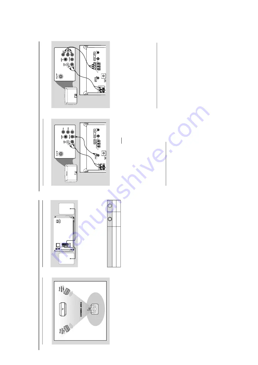
Placing speak
ers
Place the front left and
ri
ght speak
er
s at equal
distances from the
TV set and at an angle of
appro
ximately 45 degrees from the listening
position.
Notes:
–T
o avoid magnetic interfer
ence
, do not position
the fr
ont speak
er
s too c
lose to your
TV set.
–
Allo
w adequate ventilation ar
ound the D
VD Mini
Hi-Fi System.
Step 2:
Connecting speak
ers
DIN OUT
speaker
(right)
speaker
(left)
SPEAKERS 6
SUBWOOFER
OUT
Connect the speak
er wires to the SPEAKERS
(FRONT) ter
minals,
r
ight speak
er to
“
R
”
and left
speaker to
“
L
”,
coloured (mar
ked) wire to
“
+
”
and black (unmar
ked) wire to
“
–
”.
Fully inser
t
the str
ipped por
tion of the speaker wire into the
ter
minal as sho
wn.
Notes:
–F
or optimal sound perf
ormance
, use the
supplied speak
er
s.
–D
o not connect mo
re
than one speak
er to any
one pair of +/- speak
er terminals
.
–D
o not connect speak
er
s with an impedance
lower than the speak
er
s supplied.
Please refer to
the SPECIFIC
ATIONS section of this manual
.
IMPOR
T
ANT!
The type plate is located on the r
ear of
the system.
To
a
v
oid o
v
erheating of the system
, a
safety cir
cuit has been built in.
Ther
efor
e
, y
our system ma
y s
witch to
Standb
y mode automatically under
extr
eme conditions.
If this ha
ppens,
let
the system cool do
wn befor
e r
eusing it.
Speak
ers
Fr
ont Left (L)
Fr
ont Right (R)
Black
Black
White
Red
–––
–
+
Connections
Step 3:
Connecting
TV set
IMPOR
T
ANT!
–Y
ou only need to ma
ke
one
video
connection fr
om the f
ollo
wing options,
accor
ding to the capabilities of y
our TV
system.
–
S-Video or Component
Video
connection pr
o
vides higher pictur
e
quality
. These options must be a
vailab
le
on y
our
TV set.
–C
onnect the system dir
ectly to the
TV
set.
Using
Video In jack (CVBS
)
Use the composite video cab
le (y
ello
w) to
connect the system
’s
CVBS
jack to the video
input jack (or labeled as
A/V In,
Video In,
Composite or Baseband) on the
TV set.
To
listen to
TV channels through this system
, use
the audio cab
les (white/red) to connect
A
UX/
TV IN (L/R)
jacks to the cor
responding
AU
DIO OUT jacks on the
TV set.
Deactivate Progressi
ve
Scan through
System
Menu
.See page 31,
Using the Setup Menu
–
Impro
ving the image for progressi
ve
scan
video
output setting.
Y
Televisio
n
Y
AUX/
TV
IN
LINE
OUT
(CVBS)
D
D
D
P
U
UU
(
(
IMPOR
T
ANT!
–
If both S-Video and Component (Pr
Pb
Y)
Video connections ar
e used to
connect to y
our
TV set,
the
Video signal
will automaticall
y switch to S-Video
when y
ou po
w
er up the system
. T
o
set
the
VIDEO OUT (put) to
‘Pr Pb
Y’,
see
pag
e 31,
Using the Setup Menu – Setting
the
video
out.
Using component
Video In jack (Pr Pb
Y)
Use the component video cables (red/b
lue/
green) to connect the system
’s
Pr Pb
Y
jacks to
the cor
responding Component video input jacks
(or labeled as Pr/Cr Pb/Cb
Y or
YUV) on the
TV
set.
To
listen to
TV channels through this system
, use
the audio cab
les (white/red) to connect
A
UX/
TV IN (L/R)
jacks to the cor
responding
AUDIO OUT jacks on the
TV set.
If y
ou are using a Progressi
ve
Scan
TV set (TV
must indicate Progressi
ve
Scan or ProScan
capability),
activate the
PROGRESSIVE
SCAN
function through
SY
STEM MENU
.
1-7


