1.2.
Dismantling of the Front Panel
1)
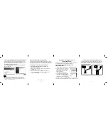
Remove 7 screws to loosen Top cover 240
.
2)
Remove 2 screws to loosen the Plate Front Loader 197. Then remove one more screw and detach the
Front Cabinet Assembly 0901 as shown in figure 3.
Figure 3 – Unscrew the screws to detach front panel
3)
Remove two more screws and detach the Plate Front Loader 197 from the Cabinet Front Assembly 0901.
The Front Panel service position is shown in Figure 4.
Figure 4 - Front Panel Service Position (Plate Front Loader detached)
Insulation Sheet
1.3.
Dismantling of the Basic Engine
1)
Remove 4 mounting screws and dismantle the Basic Engine 1001 as shown in figure 5.
Summary of Contents for DVDR3480
Page 3: ...Exploded View of the Set 3139 249 4238 110 1 a1 pdf 2007 05 07 0920 0901 ...
Page 5: ...Layout Monoboard Bottom View Monoboard Bot View 3139 243 37033 132 a3 pdf 2007 05 15 ...
Page 13: ...Monoboard Test Point Overview Monoboard Test Point 3139 243 37033 132 a3 pdf 2007 05 15 ...
Page 14: ...Layout Monoboard Top View Monoboard Top View 3139 243 37033 132 a3 pdf 2007 05 15 ...
Page 23: ...Figure 11 Mono Board Service position Insulation Sheet Insulation Sheet ...
Page 31: ......
Page 32: ......
Page 40: ......
Page 41: ......


