background image

DSATX Manual 

Copyright 2006 Mpegbox.com


  Page 7 of 13 

The DSATX is constantly monitoring the input voltage at the VIN terminal to make sure the conditions 

are right to be operating a computer motherboard in the vehicle. The DSATX will not initially turn on unless the 
voltage is above the value set by the P1 (or the serial adapter). Once the computer is up and running, the 
DSATX can survive engine cranking for up to 10 seconds. If the voltage at VIN is outside the allowable range, 
(battery too low) the DSATX will wait for sufficient charge before starting the computer and operating normally. 
The DSATX will survive engine cranking under the majority of normal use cranks. If the battery is too old or too 
depleted, there will be a point where no solution is capable of surviving engine cranking. Following the wire 
gauge and installation guidelines will provide the best results.  


3.5.3. Input Transient, and Reverse Voltage Protection 

The DSATX has components that prevent the DSATX from being damaged from the harsh conditions 

present in a motor vehicle. Transients above 24 volts (Load Dump) are shunted by the protection components. 
Reverse voltage conditions will blow the fuse before damaging components on the DSATX.  


3.5.4. Thermal Protection/Monitoring 

The DSATX is equipped with a temperature sensor that monitors the ambient temperature around the 

DSATX. The DSATX is programmed to only allow operation while the temperature is inside the window of -10c 
to 55c. If outside this range, the LED will flash 4 times and the DSATX will not provide power. Once the out of 
range condition goes away, the DSATX will behave like ACC was applied right at that point.  This protects the 
DSATX, and the computer hardware from temperature extremes and potentially damaging over and under 
temperature conditions.  


3.5.5. Output Voltage Protection/Monitoring 

The DSATX is constantly monitoring the Output Rails while operating. If the rails are ever overloaded, 

or shorted to ground or each other, the DSATX will detect that within 50ms and turn off all outputs and go into 
the “Fault” state. This will protect the computer hardware in the event that the DSATX is over loaded, or if the 
DSATX should fail for any reason. When rails are shorted, for example 5 volts to 12 volts, other power 
supplies on the market will not detect an over voltage condition, which will damage 5-volt rated computer 
components. 


3.5.6. Output Current Limiting 

The output rails of the DSATX are designed to current limit such that they will begin to sag before the 
components are overloaded beyond their manufacturer rating in a way that could cause a fire or meltdown. 
The current limiting will be detected by the continuous output voltage monitoring and trigger a fault condition. 
 

3.5.7. Sleep Mode/Battery Preservation 

When ACC goes low and stays low for a few seconds, the DSATX goes into low power Sleep Mode. In 

this state +5VSB is turned off (by default) and less than 4 mA is drawn by the DSATX. This will allow the 
DSATX equipped computer system to sit for weeks without depleting the battery. As soon as ACC goes high, 
the DSATX wakes from sleep mode.  If ACC is always tied high, the DSATX will never enter sleep mode. 


3.5.8. Start On Engine Running (VTURNON) 

When this feature is enabled with the serial adapter, the DSATX will not immediately turn on with ACC 

going high. ACC still needs to be connected as normal; however the DSATX will not turn on the computer until 
the voltage at VIN reaches 13 volts. This indicates that the alternator is charging the battery and the battery 
has sufficient charge to easily run the computer. This is useful if the system is approaching the upper limit of 
the DSATX’s capability, or if the vehicle sits for a long time. It doesn’t prevent cranking while running while 
going from the “Count Down” state back into the “Running” state, however the cranking while the vehicle has 
been sitting for a long time is the most likely to go below the 8 volt threshold of the DSATX. While the DSATX 
not surviving engine cranking is unlikely, some users like the piece of mind not worrying if “this crank” is going 
to be the one to cause a hiccup. 

 
3.5.9. AUX Output Signal 

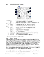
The connection at location JP1 F1,F2 can be used to provide a signal to an amplifier or auxiliary accessory 

or slave power supply (like the DSX12V) to come on after the Turn On pulse is sent. This is an open collector 
output at F1 and F2 is ground. A relay or transistor is required to deliver a 12 volt output at this location. This 
pin should sink no more than 50mA and has an allowable pull-up range of 0-25 volts. 
 

Summary of Contents for DuraWatt DSATX 220

Page 1: ...t Connectivity 8 4 1 Serial Port Adapters 8 4 2 Serial Port Overview 8 4 3 Basic Programming Control 8 4 4 Diagnostic Feed 8 4 5 Extended Basic Programming Examples 9 4 6 Advanced Features 10 4 7 Advanced Feature Tables 10 5 Specifications 11 5 1 Electrical 11 5 2 Mechanical 11 5 3 Connector Pin Locations 12 7 Mpegbox com Limited Warranty 13 1 Getting Started 1 1 Introduction Thank you for purchas...

Page 2: ...ction J5 J2 J8 DC DC Power Supply 5VSB 5V 3 3V 12V PSON 12V Adjust POTs JP1 ATX 20p 12V FAN Chassis Ground GND 12 Volts In VIN Accessory In ACC Status LED MotherBoard Switch Advanced Options Communication Port Requires RS 232 or USB Translator Control Monitoring PWROK 1 4 Included Contents and Optional Accessories Included 1 DSATX 220 Watt Power Supply 1 9 20 pin ATX Power Cable with 2 HDD Power C...

Page 3: ...MB Power Switch Computer Motherboard Hard Drive CD ROM etc 2 4 Precautions and Warnings Operating a personal computer in a motor vehicle can be dangerous Improper use or negligence can result in damage and or loss of life to self and others Safety precautions must be considered when operating a personal computer in a motor vehicle Displays must not be distracting to the driver and should not displ...

Page 4: ...odes field upgrades and diagnostics Note Do Not Over Turn P1 and P2 only 270 degrees is available 2 6 Bench Testing The DSATX can be tested in the lab before being installed into the vehicle Certain details need to be noted for proper bench testing When connecting bench power use between 12 to 16 volts DC to Vin and Gnd terminals for best results Small jumper wires may be sufficient to turn on the...

Page 5: ... to have the ability to go to the gas station and have the computer still running while you pump and pay so when you come back you don t have to wait a boot up When you get home you don t want a dead battery This power supply is the only one on the market that allows you to do all these things and have full control of the settings The following example will illustrate some of the features of Basic...

Page 6: ...ate computer is on 1 blinks Main Countdown Timer 2 blinks Power Down after shutdown pulse is sent 3 blinks N A 4 blinks Over or Under Temperature Condition Are you using a fan 5 blinks Power Supply Overload or Fault ACC must go low to clear a fault 3 4 Basic Mode Timing Diagram Accessory J5 Engine Running 5V Standby MB Power Switch JP1 Computer On t2 t3 t1 User Switch JP1 Sleep Running Count Down ...

Page 7: ... fail for any reason When rails are shorted for example 5 volts to 12 volts other power supplies on the market will not detect an over voltage condition which will damage 5 volt rated computer components 3 5 6 Output Current Limiting The output rails of the DSATX are designed to current limit such that they will begin to sag before the components are overloaded beyond their manufacturer rating in ...

Page 8: ...ke HyperTerminal or TeraTerm are examples of applications that can be used to interface with the DSATX s Extended Basic and Advanced Modes The USB adapter creates a virtual COMM Port 4 3 Basic Programming Control The DSATX responds to the following commands over the serial interface Case Sensitive E Enable Writing Parameters Allows the below commands to work P Enter Program Mode D Load Factory Def...

Page 9: ...s you can set with the P1 Pot Basically if you set the pot half way and had Maxtimer1 set to 1200 it would shutdown in 600 seconds If you set the Maxtimer1 to 0060 you would have between 0 and 60 seconds to select with the P1 Pot You must type 4 numbers Ex 0123 E ß Type the letter E Enable Writing y n y ß Type the letter y P ß Type the letter P PROGRAM MODE Use POTs y n y ß Type the letter y MAXTI...

Page 10: ...ld Y ENABLESLEEP 13 1 1 yes 0 no If set Unit Will go use Sleep Mode ACC High for Wake Up FEEDON 14 1 1 yes 0 no If set Serial Port Diagnostic Status Feed is Enabled VTURNON 15 0 1 yes 0 no If set Mb Switch Press occurs after Vin is above VINHIGHTHRESH Y ACCTIMEVAL 16 0050 10ms Settling time for the ACC input Debouncing time TEMPHIGH 17 0550 0 1 deg C Maximum Operating Temperature TEMPLOW 18 0100 0...

Page 11: ...C Input Threshold Low 4V High 7V 30V Max ACC Input Impedance 100k Ohms MB Power Switch Output Drive Open Collector 50mA Max AUX Output Drive Open Collector 50mA Max User Switch Pull Up Drive 10k Ohms to 5V Serial Port Rx Tx Low 0 7V High 2V 5V Max Supervisor Specifications Basic Mode P1 Countdown Timer Range 0 20 minutes 10 minutes default P2 Low Voltage Cutout Range 10 12 volts 11 volts default O...

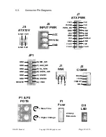
Page 12: ... 5V GND 3 3V 3 3V 5V 5V N A GND GND GND GND 12V PSON J8 ATX12V J7 ATX PWR ACC VIN GND J5 INPUT PWR 12 N C GND GND TX OUT 5VD RX IN J1 FAN J2 COMM RESET GND GND GND GND GND GND G MB_SW F AUX_SW E SL_SEN D USER_SW C USER1 B USER0 A 5VD JP1 3 3V P1 P2 POTS More Time Higher Voltage P1 P2 F1 Fuse 20 Amp Mini Auto D8 LED GND ...

Page 13: ... other consumable parts transportation costs or any damage incurred in transit This warranty will become void if the serial number identification has be wholly or partially removed or altered Repair ore replacement under the terms and conditions of this warranty does not extent the term of this warranty Any modification of the temperature control system parameters or modifications to the mechanica...

Reviews: