background image

User Manual BDL5587XL

RETURN TO THE CONTENTS

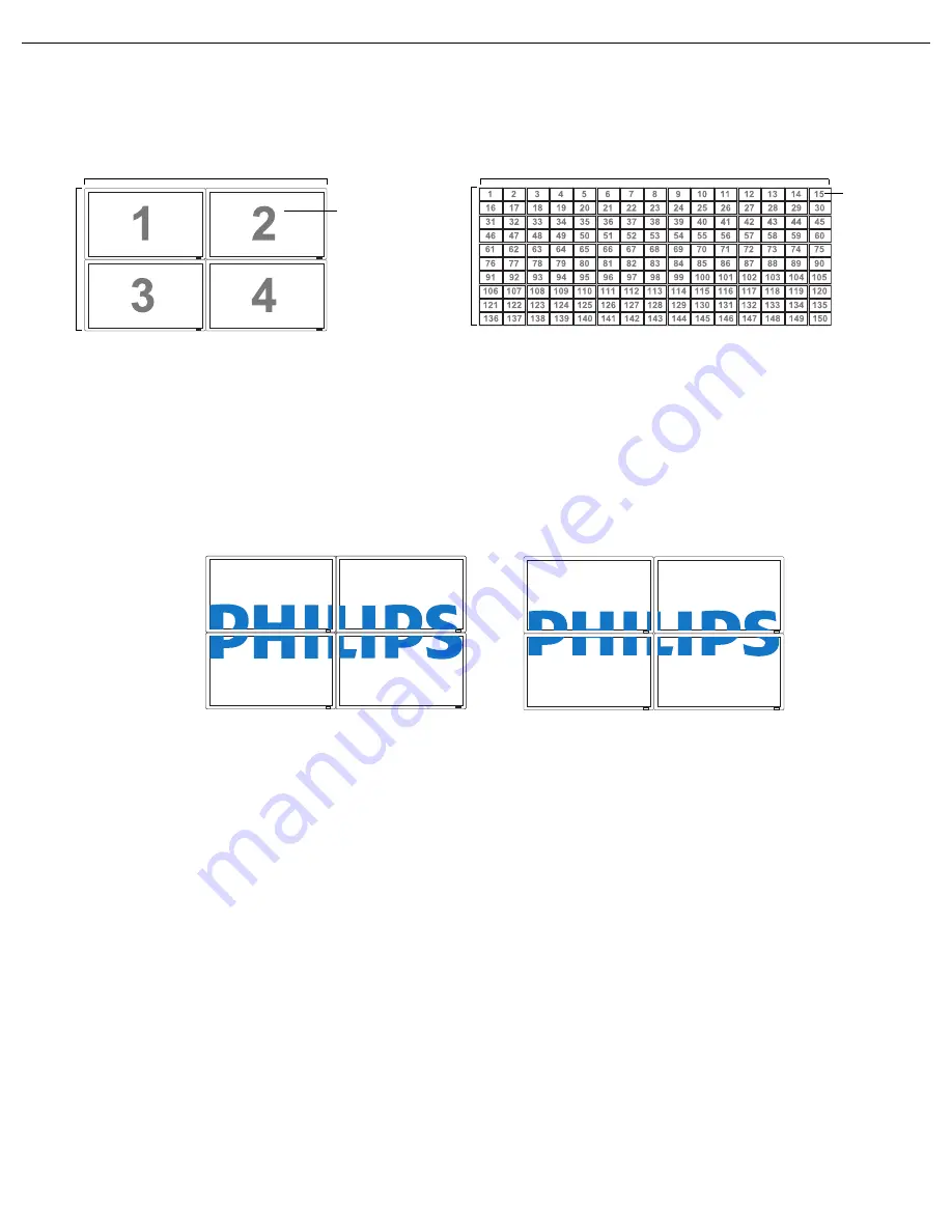
Example:

• 

H monitors

 - Select the number of displays on the horizontal side.

• 

V monitors

 - Select the number of displays on the vertical side.

• 

Position

 - Select the position of this display in the screen matrix. Position is defined by the total number of 

displays in the video wall counting from the top, left hand display and counting horizontally. The number is 
then continued on the next row down, and the procedure is continued until the final display is reached. See 
examples above for further explanation.

• 

Frame comp.

 - Choose to turn frame compensation on or off. If turned on, the display will adjust the 

image to compensate for the width of the bezels in order to accurately display the image.

• 

Enable

: Choose to enable or disable the 

Tiling

 function. If enabled, the display will apply the settings in 

monitors

V monitors

Position

, and 

Frame comp.

Note: PIP function is disabled when Tiling is enabled.

• 

Switch on delay

: Choose to enable or disable a sequence in turning on the screen matrix. If enabled, the 

display will turn on one horizontal matrix at a time starting from the top row.

Heat status

This function allows you to check the thermal status of the display at any time. The accuracy of the 
temperature indicated is  5 degrees Celsius.
Press the 

PLUS

 button to view the heat status. Press the 

EXIT

 button to return to the previous menu.

Date and time

Adjusts current date and time for the display’s internal clock.
Press the 

UP

/

DOWN

 button to toggle between the 

Year

Month

Day

Hour

Minute

, and 

Daylight 

saving time

 settings, and then press the 

PLUS

/

MINUS

 button to adjust.

Schedule

Note: Please set up current date and time in Date and time before using the Schedule function.

This function allows you to program up to seven different scheduled time intervals for the display. You can 
select the time the unit turns on and turns off, the days in a week it is activated, and which input source the 
display will use for each scheduled activation period.

H monitors

V monitors

2 x 2 screen matrix (4 displays)

H monitors = 2

V monitors = 2

10 x 15 screen matrix (150 displays)

H monitors = 15

V monitors = 10

H monitors

V moni

tors

Position

Position

Frame comp. - Off

Frame comp. - On

_+

Summary of Contents for BDL5587XL

Page 1: ...BDL5587XL www publicsignagesolutions philips com EN User manual Cleaning and troubleshooting ...

Page 2: ...o clean your display To avoid the risk of shock or permanent damage to the set do not expose the display to dust rain water or an excessively moist environment If your display becomes wet wipe it with dry cloth as soon as possible If a foreign substance or water gets in your display turn the power off immediately and disconnect the power cord Then remove the foreign substance or water and send the...

Page 3: ...y from stoves or any other heat sources Remove any object that could fall into the vents or prevent proper cooling of the display s electronics Do not block the ventilation holes on the cabinet Keep the display dry To avoid electric shock do not expose it to rain or excessive moisture When turning off the display by detaching the power cable or DC power cord wait for 6 seconds before re attaching ...

Page 4: ...f not installed and used in accordance with the instructions may cause harmful interference to radio communications However there is no guarantee that interference will not occur in a particular installation If this equipment does cause harmful interference to radio or television reception which can be determined by turning the equipment off and on the user is encouraged to try to correct the inte...

Page 5: ...dards PN 93 T 42107 and PN 89 E 06251 ELECTRIC MAGNETIC AND ELECTRONMAGNETIC FIELDS EMF 1 MMD manufactures and sells many products targeted at consumers which like any electronic apparatus in general have the ability to emit and receive electromagnetic signals 2 One of MMD s leading Business Principles is to take all necessary health and safety measures for our products to comply with all applicab...

Page 6: ...ould not be greater than 5A Note Any severed plug must be destroyed to avoid a possible shock hazard should it be inserted into a 13A socket elsewhere How to connect a plug The wires in the mains lead are coloured in accordance with the following code BLUE NEUTRAL N BROWN LIVE L GREEN YELLOW EARTH E 1 The GREEN AND YELLOW wire must be connected to the terminal in the plug which is marked with the ...

Page 7: ...6 标准规定的限量要求 环保使用期限 此标识指期限 十年 电子信息产品中含有的有毒有害物质或元素在正常使用的条件下不会发生外泄或突变 电子信息产品用户使用该电子信息产品不会对环境造成严重污染或对其人身 财产造成严重损害的期限 废弃电器电子产品回收处理管理条例 提示性说明 为了更好地关爱及保护地球 当用户不再需要此产品或产品寿命终止时 请遵守国家废弃电器电子产品回收处 理相关法律法规 将其交给当地具有国家认可的回收处理资质的厂商进行回收处理 部件名称 有毒有害物质或元素 铅 Pb 汞 Hg 镉 Cd 六价铬 Cr 6 多溴联苯 PBB 多溴二苯醚 PBDE 外壳 O O O O O O 液晶面板 X X O O O O 电路板组件 X O O O O O 附件 遥控器 电源线 连接线 X O O O O O 遥控器电池 X O O O O O ...

Page 8: ...ww eia org Consumer Education Initiative WASTE ELECTRICAL AND ELECTRONIC EQUIPMENT WEEE Attention users in European Union private households This marking on the product or on its packaging illustrates under European Directive 2002 96 EG governing used electrical and electronic appliances that this product may not be disposed of with normal household waste You are responsible for the disposal of th...

Page 9: ... A PC 3 4 1 USING VGA INPUT 3 4 2 USING DVI INPUT 3 4 3 USING HDMI INPUT 3 4 4 USING DISPLAY PORT INPUT 3 4 5 USING a DVI D Out to HDMI IN connection 3 5 EXTERNAL AUDIO CONNECTION 3 5 1 CONNECTING EXTERNAL SPEAKERS 3 5 2 CONNECTING EXTERNAL AUDIO DEVICE 3 6 CONNECTING ANOTHER BDL5587XL DISPLAY 4 OSD MENU 4 1 NAVIGATING THE OSD MENU 4 1 1 NAVIGATING THE OSD MENU USING THE REMOTE CONTROL 4 1 2 NAVIG...

Page 10: ... 4 DARK DOT DEFECTS 6 5 PROXIMITY OF PIXEL DEFECTS 6 6 PIXEL DEFECT TOLERANCES 6 7 MURA 6 7 1 HOW TO SPOT MURA 6 7 2 HOW TO AVOID MURA 7 CLEANING AND TROUBLESHOOTING 7 1 CLEANING 7 2 TROUBLESHOOTING 8 TECHNICAL SPECIFICATIONS ...

Page 11: ... shipped to another location External speakers and table stands are offered as optional extras and therefore not included with your display 1 3 INSTALLATION NOTES The product should be installed on a flat surface to avoid tipping Maintain a distance of at least 6cm between the back of the display and the wall for proper ventilation Avoid installing the unit in a kitchen bathroom or any other place...

Page 12: ... should comply with the UL1678 standard in North America The mounting means should be strong enough to bear the weight of the display approx 34 kg 75 0 lb without stands Note The AC IN OUT socket should be on top of all connectors when rotating your display Allowable tilting angle in Portrait Mode Note When installing the display on the wall please consult a professional technician for proper inst...

Page 13: ...k or unlock all buttons 4 button When the On Screen Display menu is active use these as the PLUS MINUS menu buttons 5 POWER button Use this button to turn the display on or into standby mode 6 Power indicator Indicates the operating status of the unit lights green when the display is turned on lights red when the display is in standby mode blinks red when the display enters DPMS mode off when the ...

Page 14: ...etects the ambient lighting conditions around the display Indicates the operating status of the unit lights green when the display is turned on lights red when the display is in standby mode blinks red when the display enters DPMS mode off when the main power of the display is turned off 10 Carrying handle Use these handles when lifting or moving your display ...

Page 15: ...o input YPbPr for connecting to the component output of an AV device 9 VGA OUT Outputs the VGA signal from the VGA IN jack 10 VGA IN Connects to the VGA output of a PC or media player 11 DVI D OUT Outputs the DVI D signal from the DVI D IN jack 12 DVI D IN Connects to the DVI I connector of a PC receiving only the DVI D signal or to the HDMI output of an AV device Using a DVI HDMI cable 13 DISPLAY...

Page 16: ...ing images such as Video Standard for images factory setting sRGB for text based images Cinema for movies User create your own picture settings This mode is automatically selected after you change the settings in the Picture menu VIDEO SOURCE button Press to open the video source selection menu and then press UP DOWN to select a desired video signal AUDIO SOURCE button Press to open the audio sour...

Page 17: ...move the highlight bar down to adjust the selected item when OSD menu is on To move the sub picture down in PIP mode PLUS button To increase the adjustment within the OSD menu To move the sub picture right in PIP mode MINUS button To decrease the adjustment within the OSD menu To move the sub picture left in PIP mode SET button To activate the changed settings inside the OSD menu AUTO ADJUST butto...

Page 18: ...ntrol sensor Use the remote control within a maximum distance of about 10 m 32 8 ft perpendicular to the display s remote control sensor and within a maximum angle of 45 degrees Notes The effective range declines with the increase of distance and angle Because this is a zero bezel display the IR sensor is placed at the back of the unit To optimize the functionality of the IR remote we suggest the ...

Page 19: ...witch cover to prevent the monitor from being turned on or off accidentally 3 3 CONNECTING EXTERNAL EQUIPMENT DVD VCR VCD 3 3 1 USING COMPONENT VIDEO INPUT 1 Connect the BNC jacks of the device to the BNC jacks YPbPr of the display 2 Connect the red R and white L audio jacks of the device to the AUDIO IN AUDIO2 or AUDIO3 jacks of the display DVD VCR VCD ...

Page 20: ...external device to the HDMI input of the display 3 4 CONNECTING A PC 3 4 1 USING VGA INPUT 1 Connect the 15 pin VGA connector of the PC to the VGA IN connector of the display 2 Insert the audio cable to the AUDIO IN AUDIO1 input of the display and connect to the corresponding PC connector DVD Blu ray PC ...

Page 21: ...r 3 4 3 USING HDMI INPUT 1 Connect the HDMI connector of the PC to the HDMI connector of the display using an HDMI cable 3 4 4 USING DISPLAY PORT INPUT 1 Connect the Display port DVI VGA HDMI connector of the PC to the DISPLAY PORT connector of the display using a Display port to Display port cable or Display port to DVI VGA HDMI adaptor 2 Insert the audio cable to the AUDIO IN AUDIO1 input of the...

Page 22: ... port to Display port cable or Display port to HDMI adaptor 3 4 5 USING a DVI D Out to HDMI IN connection 1 Connect the DVI connector of the PC to the HDMI connector of the display using a DVI HDMI cable 2 Insert the audio cable to the AUDIO IN AUDIO1 input of the display and connect to the corresponding PC connector PC PC ...

Page 23: ... the external speaker SPEAKERS output of the display 2 Turn on the unit Note Make sure your display is turned off before connecting the speaker wires 3 5 2 CONNECTING EXTERNAL AUDIO DEVICE Connect the red R and white L audio jacks of the external audio device to the AUDIO OUT R L jacks of the display External speakers External audio device ...

Page 24: ...tional BDL5587XL unit Note You can connect up to 5 displays using the VGA OUT connectors Connect the RS 232C OUT connector of the display to the RS 232C IN connector of an additional BDL5587XL unit Connect the DVI D OUT connector of the display to the DVI D IN connector of an additional BDL5587XL unit Note You can connect up to 9 displays using the DVI D OUT connectors To ensure optimal image qual...

Page 25: ... the MENU button on the remote control to display the OSD menu 2 Press the UP DOWN button to move the cursor to the item you want to adjust 3 Press the PLUS SET button to enter the submenu 4 In the submenu press the UP DOWN button to toggle between items or press the PLUS MINUS button to adjust settings If there is a submenu press the PLUS button to enter it 5 Press the MINUS EXIT button on the re...

Page 26: ...utton to move the cursor to the item you want to adjust 3 Press the button to enter the submenu 4 In the submenu press the button to toggle between items or press button to adjust settings If there is a submenu press the button to enter it 5 Press the MENU button on the remote control to return to the previous menu or press the MENU button repeatedly to exit the OSD menu ...

Page 27: ... the PLUS MINUS button to adjust Noise reduction Note For Component input with interlaced video only Adjust to remove the noise in the image You can select a suitable noise reduction level Use the UP DOWN button to make selection Tint Note For Component and HDMI inputs with YUV color space only YUV is a color space typically used as part of a color image pipeline Adjust to change the color tint of...

Page 28: ...t lighting conditions change Use the UP DOWN button to make selection Smart contrast Note This function is not available when Light sensor or Brightness under Panel saving is turned on Disable these functions to make Smart contrast accessible from the OSD menu When turned on this function helps enhance image contrast when displaying dark scenes Use the UP DOWN button to make selection Smart pictur...

Page 29: ...utton to adjust Zoom mode The pictures you receive may be transmitted in 16 9 format widescreen or 4 3 format conventional screen 16 9 pictures sometimes have a black band at the top and bottom of the screen letterbox format This function allows you to optimize the picture display on screen The following zoom modes are available Full This mode restores the correct proportions of pictures transmitt...

Page 30: ...e settings to factory preset values Press the EXIT button to cancel and return to the previous menu 21 9 The picture is enlarged to 21 9 format This mode is recommended when displaying pictures that have black bands at the top and bottom letterbox format Note This mode does not support deinterlacing The screen may flicker when displaying interlaced video Zoom Expands the horizontal and vertical si...

Page 31: ...crease or decrease the audio balance level Use the PLUS MINUS button to adjust Treble Adjust to increase or decrease the treble Use the PLUS MINUS button to adjust Bass Adjust to increase or decrease the bass Use the PLUS MINUS button to adjust Mute Turns the mute function on off Use the UP DOWN button to make selection Audio source Select the audio input source toggle between audio input DISPLAY ...

Page 32: ...io reset Reset all settings in the Audio menu Use the PLUS MINUS button to make selection Select Reset and press the SET button to restore settings to factory preset values Press the EXIT button to cancel and return to the previous menu Audio 3 HDMI ...

Page 33: ... Display Power Management Signaling mode when no signal can be detected from the HDMI DVI D and VGA inputs after three successive cycles Use the PLUS MINUS button to make selection Video Select On to let the display enter power saving mode when no signal is detected from the Component input after three successive cycles Use the PLUS MINUS button to make your selection Language Select the language ...

Page 34: ...outer 2 Enter the submenu of Network settings You will see the OSD page similar to the following picture 3 Use the UP DOWN PLUS MINUS buttons to set the Network device name 4 If you are in a DHCP environment highlight DHCP and select Enable Once selected the IP address Subnet mask and Default gateway settings will be displayed If you are not in a DHCP environment highlight DHCP and select Disable ...

Page 35: ...ssword menu and press Login If the password has not been set enter the default 000000 3 The setting page appears Power Setup Allows you to manage the power status Note Make sure the LAN control port in the Configuration 1 Network settings menu is set to Enable if you would like to turn on the display from this web page A V Setup Provides various options for video and audio control Configuration Se...

Page 36: ...button to make selection Select Reset and press SET to restore settings to factory preset values Press EXIT to cancel and return to the previous menu Factory reset Reset all settings in the Picture Screen Audio PIP Configuration 1 Configuration 2 and Advanced option menus restoring them to factory preset values Use the PLUS MINUS button to make selection Select Reset and press SET to restore setti...

Page 37: ...n Off is selected If 0 is selected the information OSD will remain on the screen Sleep timer Set the display to turn itself off to standby mode within a user specified amount of time Off 24 hours from current time Use the UP DOWN button to adjust Note When the Sleep timer is activated Schedule settings will be disabled OSD H position Adjust the horizontal position of the OSD menu Use the UP DOWN b...

Page 38: ...erly can appear too white or too dark so controlling the gamma properly can have a huge influence on the overall picture quality of your display Select a display gamma value to best suit the image and optimize image brightness and contrast Use the UP DOWN button to toggle between Scan mode Note For Component and HDMI video mode inputs only Change the display area of the image Use the UP DOWN butto...

Page 39: ... this display will be operated by the remote control Secondary Designate this display as the secondary unit This display can not be operated by the remote control and will only receive the control signal from the primary unit via the RS232C connection Lock Lock the remote control function of this display To unlock press and hold the DISPLAY button on the remote control for 5 seconds IR out Select ...

Page 40: ...ning on the screen matrix If enabled the display will turn on one horizontal matrix at a time starting from the top row Heat status This function allows you to check the thermal status of the display at any time The accuracy of the temperature indicated is 5 degrees Celsius Press the PLUS button to view the heat status Press the EXIT button to return to the previous menu Date and time Adjusts curr...

Page 41: ...s the PLUS button to highlight the Off item Press the SET button and then press the UP DOWN button to set the power off hour to 22 6 Press the PLUS button to move to the minute slot Press the UP DOWN button to set the power off minute to 30 then press the EXIT button 7 Press the PLUS button to highlight the Input item and then press the UP DOWN button to select HDMI 8 Press the PLUS button to sele...

Page 42: ...schedule item has priority For example if schedule items 1 and 2 both set the display to power on at 7 00 AM and off at 5 00 PM then only schedule item 1 will take effect Monitor ID Set the ID number for controlling the unit via the RS232C connection Each display must have a unique ID number when multiple BDL5587XL units are connected Each monitor s ID is defined by its position within the matrix ...

Page 43: ... the UP DOWN button to make selection Settings cloning Select Monitor to USB or USB to Monitor to transfer all the OSD settings between the display and a USB flash drive Advanced option reset Reset all settings in the Advanced option menu Press the PLUS button to open the submenu and then press PLUS MINUS to make selection Select Reset and press the SET button to restore settings to factory preset...

Page 44: ...t Yes to start update A status message appears 7 After the update process completes the display will re start automatically Notes The display does not support USB flash drives with NTFS format Do not turn off the display during the update process It may damage the display if you do If the error message appears on the Firmware Update OSD menu please make sure that the USB flash drive is properly pl...

Page 45: ...ray 75 Hz 78 75 MHz WXGA 1280 768 60 Hz 79 5 MHz 5 3 Wide XGA WXGA 1280 800 60 Hz 79 5 MHz 16 10 Wide XGA SXGA 1280 960 60 Hz 108 MHz 4 3 Super XGA SXGA 1280 1024 60 Hz 108 MHz 5 4 Super XGA WXGA 1360 768 60 Hz 85 5 MHz 16 9 Wide XGA WXGA 1366 768 60 Hz 85 5 MHz 16 9 Wide XGA UXGA 1600 1200 60 Hz 162 MHz 4 3 Ultra XGA HD1080 1920 1080 60 Hz 148 5 MHz 16 9 HD1080 Standard Resolution Active Resoluti...

Page 46: ...he screen when the PC power is turned off or if the PC is disconnected If this happens press the INPUT button to enter the video mode Also make sure that the PC is connected If horizontal synchronous signals seem irregular in RGB mode check PC power saving mode or cable connections The display settings table complies with IBM VESA standards and based on analog input ...

Page 47: ...pes or combinations of pixel defects are more noticeable than others Philips sets even higher quality standards for those 6 1 PIXELS AND SUB PIXELS A pixel or picture element is composed of three sub pixels in the primary colors of red green and blue Many pixels together form an image When all sub pixels of a pixel are lit the three colored sub pixels together appear as a single white pixel When a...

Page 48: ...eding the tolerances listed in the following table 6 7 MURA Dark spots or patches may occasionally appear on some liquid crystal display LCD panels This is known within the industry as Mura which is a Japanese term for unevenness It is used to describe an irregular pattern or area in which uneven screen uniformity appears under certain conditions Mura is a result of the deterioration of the liquid...

Page 49: ...e listed below Impurities or foreign particles in the crystal matrix Uneven distribution of LCD matrix during manufacturing Non uniform luminance distribution of the backlight Panel assembly induced stress Flaws within the LCD cells Thermal induced stress high temperature operation over long periods of time 6 7 2 HOW TO AVOID MURA Although we can not guarantee the complete eradication of Mura ever...

Page 50: ...eaning cloth or a soft lint free cloth If the surface becomes dirty soak a soft lint free cloth in a mild detergent solution Wring the cloth to remove excess liquid Wipe the surface of the display to remove dirt Then use a dry cloth of the same type to dry Do not scratch or hit the surface of the panel with fingers or hard objects of any kind Do not use volatile substances such as sprays solvents ...

Page 51: ... zoom mode is not correctly set Use the Zoom mode or Custom zoom function in the Screen menu to fine tune display geometry and time frequency parameter Can hear sound but no picture Improperly connected source signal cable Make sure that both video inputs and sound inputs are correctly connected Can see picture but no sound is heard 1 Improperly connected source signal cable 2 Volume is turned all...

Page 52: ...V rms Normal 2 Channel L R RS232C Input D Sub Jack x 1 9 pin TXD RXD 1 1 HDMI Input HDMI Jack x 1 Type A Version 1 3 Digital RGB TMDS Video Audio MAX Video 720p 1080p 1920 x 1080 60 Hz WUXGA Audio 48 KHz 2 Channel L R DVI D Input DVI I jack Digital RGB TMDS Video VGA Input D Sub Jack x 1 15 pin Analog RGB 0 7V p p 75 H CS V TTL 2 2k SOG 1V p p 75 MAX 720p 1080p 1920 x 1080 60 Hz WUXGA 3 5mm Mini j...

Page 53: ...V 240V 50 60 Hz Power Consumption Max 250W Display Dimension W x H x D Without Stand mm inch 1215 2 x 686 x 125 35 47 8 x 27 x 5 Gross Weight kg lbs Net Weight kg lbs 41 85 98 33 72 6 Regulatory CB EMC CE C Tick EPA EuP EMF CCC CECP CEL UL cUL EMC FCC ICES003 E Star GOST WEEE Accessories CD user s Manual QSG Power cord VGA Cable BNC to RCA adapter x3 Cable retainer x3 Remote control with batteries...

Page 54: ...User Manual BDL5587XL RETURN TO THE CONTENTS ...

Reviews: