background image

BDL3245E / BDL4245E / BDL4645E

v

Information for U.K. only

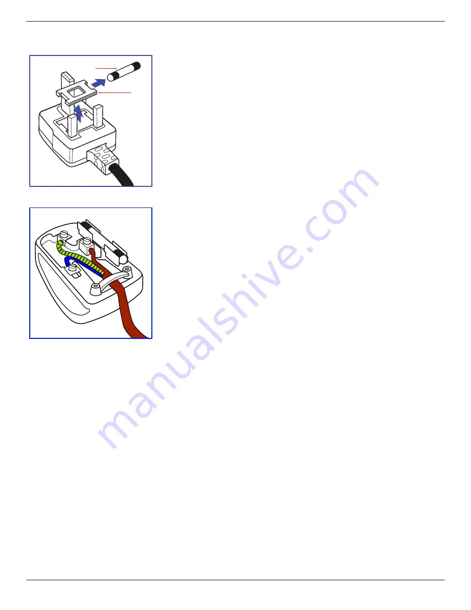
(A)

(B)

WARNING - THIS APPLIANCE MUST BE EARTHED.
Important:

This apparatus is supplied with an approved moulded 13A plug. To change a fuse in this type of plug 

proceed as follows:
1.  Remove fuse cover and fuse.
2.  Fit new fuse which should be a BS 1362 5A,A.S.T.A. or BSI approved type.
3. 

Refit the fuse cover.

If the fitted plug is not suitable for your socket outlets, it should be cut off and an appropriate 3-pin 

plug fitted in its place.

If the mains plug contains a fuse, this should have a value of 5A. If a plug without a fuse is used, the fuse 

at the distribution board should not be greater than 5A.
NOTE:   The severed plug must be destroyed to avoid a possible shock hazard should it be inserted 

into a 13A socket elsewhere.

How to connect a plug

The wires in the mains lead are coloured in accordance with the following code:

BLUE - “NEUTRAL” (“N”)
BROWN - “LIVE” (“L”)
GREEN & YELLOW - “EARTH” (“E”)

1.  The GREEN & YELLOW wire must be connected to the terminal in the plug which is marked with 

the letter “E” or by the Earth symbol or coloured GREEN or GREEN & YELLOW.

2.  The BLUE wire must be connected to the terminal which is marked with the letter “N” or coloured 

BLACK.

3.  The BROWN wire must be connected to the terminal which marked with the letter “L” or 

coloured RED.

Before replacing the plug cover, make certain that the cord grip is clamped over the sheath of the lead 

- not simply over the three wires.

Summary of Contents for BDL4245E

Page 1: ...www philips com welcome BDL3245E BDL4245E BDL4645E User Manual English ...

Page 2: ...be easily accessible Read and follow these instructions when connecting and using your Public Information Display Unplug the display if you are not going to use it for an extensive period of time Unplug the display if you need to clean it with a slightly damp cloth The screen many be wiped with a dry cloth when the power is off However never use alcohol solvents or ammonia based liquids Consult a ...

Page 3: ...ned to provide reasonable protection against harmful interference when the equipment is operated in a commercial environment This equipment generates uses and can radiate radio frequency energy and if not installed and used in accordance with the instructions manual may cause harmful interference to radio communications Operation of this equipment in a residential area is likely to cause harmful i...

Page 4: ...ents of standards PN 93 T 42107 and PN 89 E 06251 Electric Magnetic and Electronmagnetic Fields EMF 1 We manufacture and sell many products targeted at consumers which like any electronic apparatus in general have the ability to emit and receive electromagnetic signals 2 One of our leading Business Principles is to take all necessary health and safety measures for our products to comply with all a...

Page 5: ...n board should not be greater than 5A NOTE The severed plug must be destroyed to avoid a possible shock hazard should it be inserted into a 13A socket elsewhere How to connect a plug The wires in the mains lead are coloured in accordance with the following code BLUE NEUTRAL N BROWN LIVE L GREEN YELLOW EARTH E 1 The GREEN YELLOW wire must be connected to the terminal in the plug which is marked wit...

Page 6: ...O O O O 附件 遥控器 电源线 连接线 X O O O O O 遥控器电池 X O O O O O O 表示该有毒有害物质在该部件所有均质材料中的含量均在 SJ T11363 2006 标准规定的限量要求以下 X 表示该有毒有害物质至少在该部件的某一均质材料中的含量超出 SJ T11363 2006 标准规定的限量要求 10 環保使用期限 此標識指期限 十年 電子信息產品中含有的有毒有害物質或元素在正常使用的條件下不會發生外泄或突變 電子信息產品用戶使用該電子信息產品不會對環境造成嚴重污染或對其人身 財產造成嚴重損害的期限 中国能源效率标识 根据中国大陆 能源效率标识管理办法 本显示器符合以下要求 能源效率 cd W 1 05 能效等级 1 级 能效标准 GB 21520 2008 详细有关信息请查阅中国能效标识网 http www energylabel gov cn ...

Page 7: ...umer Education Initiative Waste Electrical and Electronie Equipment WEEE Attention users in European Union private households This marking on the product or on its packaging illustrates that under European Directive 2002 96 EG governing used electrical and electronic appliances this product may not be disposed of with normal household waste You are responsible for disposal of this equipment throug...

Page 8: ...ion 1 1 1 Unpacking 1 1 2 Package Contents 1 1 3 Installation Notes 1 1 4 Installing and RemovingTable Stands optional 2 1 5 Mounting on a Wall 3 1 6 Mounting in Portrait Position 4 1 6 1 How to use the logo guider for portrait position 4 1 6 2 How to remove the logo 4 2 Parts and Functions 5 2 1 Control Panel 5 2 2 Input OutputTerminals 6 2 3 Remote Control 7 2 3 1 General functions 7 2 3 2 Inser...

Page 9: ...e Control and AAA Batteries Video Signal Cable D SUB to D SUB Cable Logo guider CD ROM Power switch cover Screw for Power switch cover M3 x 8 x 1 BNC RCA adapter x 5 NOTES Please make sure that for all other regions apply a power cord that conforms to the AC voltage of the power socket and has been approved by and complies with the safety regulations of the particular country You might like to sav...

Page 10: ...g the stand in the guide block tighten the screws on both sides of the display NOTE The longer side of the stand should face the front of the display Thumbscrews Carrying handle Longer portions face the front Table stand To remove table stands 1 Power off the display 2 Spread a protective sheet on a flat surface 3 Grab the carrying handles and place the display face down on the protective sheet 4 ...

Page 11: ...age to the equipment or injury to the user or installer Product warranty does not cover damage caused by improper installation 4 For the wall mounting kit use M6 mounting screws having a length 10 mm longer than the thickness of the mounting bracket and tighten them securely Caution To prevent the display from falling For wall or ceiling installation we recommend installing the display with metal ...

Page 12: ...er Hold and press the guider with your left hand Put the logo sticker with its adhesive side down into the logo hole with your right hand and press to make it stick tightly onto the front bezel 3 Remove the guider 1 2 3 1 6 2 How to remove the logo 1 Prepare a piece of paper with a cutting area of logo as a protector to prevent the front bezel from scratching 2 Using a knife carefully remove the l...

Page 13: ...ove the highlight bar down to adjust the selected item while OSD menu is on 8 MENU button Return to previous menu while OSD menu is on or to activate the OSD menu when OSD menu is off NOTE Keyboard Control Lock Mode This function completely disables the access to all Keyboard Control functions To enable or disable the keyboard control lock press both and buttons and hold down continuously for more...

Page 14: ...VI HDMI cable 7 HDMI IN Connect the HDMI output of an AV device or the DVI D output of a PC by using a DVI HDMI cable 8 VGA IN D Sub Connect the computerVGA output 9 COMPONENT IN BNC Connect the componentYPbPr output from external AV device 10 AUDIO IN 1 2 3 Connect audio input from external AV device AUDIO IN 1 3 5mm stereo phone jack AUDIO IN 2 3 RCA phone jack 11 VIDEO IN OUT S VIDEO IN Mini DI...

Page 15: ...T button Press to run the Auto Adjust function NOTE This button is functional forVGA input only 9 MUTE button Press to turn the mute function on off 10 VIDEO SOURCE button Press to toggleVideo Source Menu Press or button to select one of the video sources among HDMI DVI D VGA Component S Video or Video Press SET button to confirm and exit 11 AUDIO SOURCE button Press to toggle Audio Source Menu Pr...

Page 16: ...f you do not intend to use the remote control for a long period remove the batteries 2 3 3 Handling the remote control Do not subject to strong shock Do not allow water or other liquid to splash the remote control If the remote control gets wet wipe it dry immediately Avoid exposure to heat and steam Other than to install the batteries do not open the remote control 2 3 4 Operating range of the re...

Page 17: ...witch is provided to prevent the display from being turned on or off accidentally To lock the cover into position 1 Align and insert the cover to the indentation located beside the power switch 2 Use the screw to lock the cover BDL3245E 1 2 Screw Power switch cover BDL4245E BDL4645E 1 2 Screw Power switch cover ...

Page 18: ... 10 3 2 Connecting External Equipment DVD VCR VCD 3 2 1 Using COMPONENT video input Audio Output To AUDIO IN 2 3 DVD VCR VCD COMPONENT YPbPr COMPONENT YPbPr 3 2 2 Using HDMI video input DVD VCR VCD HDMI connector HDMI connector ...

Page 19: ...ing a PC 3 3 1 Using VGA input To VGA IN PC or IBM compatible From analog VGA output Mini D Sub 15 pin From audio output To AUDIO IN 1 2 3 3 3 2 Using DVI input From audio output To DVI IN PC or IBM compatible From DVI output To AUDIO IN 1 2 3 ...

Page 20: ...BDL3245E BDL4245E BDL4645E 12 3 3 3 Using HDMI input To HDMI IN PC or IBM compatible From HDMI output ...

Page 21: ...BDL3245E BDL4245E BDL4645E 13 3 4 External Audio Connection 3 4 1 Connecting external speakers External speaker 3 4 2 Connecting an external audio device Stereo Amplifier RCA Audio In To AUDIO OUT ...

Page 22: ...of display 2 Connect the VGA OUT connector of display 1 to the VGA IN connector of display 2 Connect the VIDEO OUT connector of display 1 to the VIDEO IN connector of display 2 To RS 232C IN RS 232C Cable PC To RS 232C OUT To RS 232C IN RS 232C Cable 3 5 2 Audio connection Do one the following connections Connect the AUDIO OUT connector of display 1 to the AUDIO IN 2 OR AUDIO IN 3 connector of dis...

Page 23: ... contrast Smart picture Picture Screen Audio PIP Configuration1 Configuration2 Advanced option Noise reduction Brightness Adjust the overall image brightness by changing the intensity of the LCD panel s backlight Contrast Adjust to sharpen the picture quality The black portions of the picture become richer in darkness and the white become brighter Sharpness Adjust to improve the image detail Black...

Page 24: ...ows you to optimize the picture display on screen The following zoom modes are available for PC mode Full Normal Custom Real Video mode Full Normal Dynamic Custom Real 21 9 NOTE If the function for pixel shift andTiling enabled the menu items for Zoom mode H position V position will be disabled Full This mode restores the correct proportions of pictures transmitted in 16 9 using the full screen di...

Page 25: ...ions are Off PIP POP PBP aspect PBP full PIP input Select the input signal for the sub picture PIP change Enlarges the smaller picture to become the main picture and vice versa PIP size Select the size of the sub picture in the PIP Picture in Picture mode The options are Small Medium Large PIP audio Select the audio source in the PIP Picture in Picture mode Main Select audio from the main picture ...

Page 26: ...ches 79 C 174 F All key function except Power key will then be disabled Brightness Select On and the brightness of the image will be reduced to an appropriate level and the Brightness setting in the Picture menu will become unavailable Pixel shift Select the time interval Auto 10 900 Seconds Off for the display to slightly expand the image size and shift the position of pixels in four directions u...

Page 27: ...on Input resolution Set the resolution of theVGA input This is only required when the display is unable to detect theVGA input resolution correctly NOTE This item is functional forVGA input only The options are 1024x768 1280x768 1360x768 1400x1050 1680x1050 1600x1200 1920x1200 Auto Determines the resolution automatically The selected settings will become effective after turning off the power and t...

Page 28: ...f this display To unlock press and hold the DISPLAY button on the remote control for 5 five seconds Keyboard control Choose to enable or disable the display keyboard control buttons function Lock Disable the keyboard function Lock All Lock all butVolume Lock all but Power Disable the keyboard function Tiling With this function you can create a single large screen matrix video wall that consists of...

Page 29: ...et clock 2011 08 04 20 20 1 Press button to enter the submenu 2 Press or button to toggle among the Year Month Day Hour Minute and Daylight saving time settings 3 Press or button to adjust all settings except Daylight saving time 4 Press SET button to enter the Daylight saving submenu 5 Press or button to select item press or button to adjust Schedule This function allows you to program up to 7 se...

Page 30: ...em 1 will take effect Monitor ID Set the ID number for controlling the display via the RS232C connection Each display must have a unique ID number when multiple sets of this display are connected DDC CI Choose to turn on or off the DDC CI communication function Select On for normal use Smart power Set the display to reduce the power consumption automatically The options are Off Medium High Auto si...

Page 31: ...576p 50 Hz 27 MHz HDTV Resolution Standard Resolution Active Resolution Refresh Rate Pixel Rate Aspect Ratio Stand for Mode H Pixels V Lines 720p 1280 720 50 Hz 74 25 MHz 16 9 Normally DVB Mode 60 Hz 1080i 1920 1080 25 Hz 74 25 MHz 16 9 Normally ATSC Mode 30 Hz 1080p 1920 1080 50 Hz 148 5 MHz 16 9 Normally ATSC Mode 60 Hz The PC text quality is optimum in HD 1080 mode 1920 x 1080 60Hz Your PC disp...

Page 32: ...l pixel A pixel or picture element is composed of three sub pixels in the primary colors of red green and blue Many pixels together form an image When all sub pixels of a pixel are lit the three colored sub pixels together appear as a single white pixel When all are dark the three colored sub pixels together appear as a single black pixel Other combinations of lit and dark sub pixels appear as sin...

Page 33: ...ear on some liquid crystal display LCD panels This is known within the industry as Mura which is a Japanese term for unevenness It is used to describe an irregular pattern or area in which uneven screen uniformity appears under certain conditions Mura is a result of the deterioration of the liquid crystal alignment layer and is most commonly caused by long term operation under high ambient tempera...

Page 34: ... a soft lint free cloth If the surface becomes dirty soak a soft lint free cloth in a mild detergent solution Wring the cloth to remove excess liquid Wipe the surface of the display to remove dirt Then use a dry cloth of the same type to dry Do not scratch or hit the surface of the panel with fingers or hard objects of any kind Do not use volatile substances such as insert sprays solvents and thin...

Page 35: ...n The zoom mode is not correctly set Use the Zoom mode or Custom zoom function in the Screen menu to fine tune display geometry and time frequency parameter Can hear sound but no picture Improperly connected source signal cable Make sure that both video inputs and sound inputs are correctly connected Can see picture but no sound is heard 1 Improperly connected source signal cable 2 Volume is turne...

Page 36: ...0p 1080p 1920 x 1080 60 Hz WUXGA Audio 48 KHz 2 Channel L R Supports LPCM only DVI D Input DVI D jack Digital RGB TMDS Video VGA Input D Sub Jack x 1 15 pin Analog RGB 0 7V p p 75Ω H CS V TTL 2 2kΩ SOG 1V p p 75Ω MAX 720p 1080p 1920 x 1080 60 Hz WUXGA VGA Output D Sub Jack x 1 15 pin Analog RGB 0 7V p p 75Ω H CS V TTL 2 2kΩ SOG 1V p p 75Ω MAX 720p 1080p 1920 x 1080 60 Hz WUXGA Component Input BNC ...

Page 37: ...C Storage 20 60 C Humidity Operational 20 80 RH No condensation Storage 5 95 RH No condensation Altitude Operational 0 3 000 m Storage Shipment 0 9 000 m Internal Speaker Item Specifications Type 1 Way 1 Speaker Input 10 W RMS Impedance 8Ω Output Sound Pressure 82 dB W M Frequency Response 160 Hz 13 KHz ...

Page 38: ... 1080 60 Hz WUXGA Audio 48 KHz 2 Channel L R Supports LPCM only DVI D Input DVI D jack Digital RGB TMDS Video VGA Input D Sub Jack x 1 15 pin Analog RGB 0 7V p p 75Ω H CS V TTL 2 2kΩ SOG 1V p p 75Ω MAX 720p 1080p 1920 x 1080 60 Hz WUXGA VGA Output D Sub Jack x 1 15 pin Analog RGB 0 7V p p 75Ω H CS V TTL 2 2kΩ SOG 1V p p 75Ω MAX 720p 1080p 1920 x 1080 60 Hz WUXGA Component Input BNC Jack x 3 Y 1V p...

Page 39: ...rational 0 40 C Storage 20 60 C Humidity Operational 20 80 RH No condensation Storage 5 95 RH No condensation Altitude Operational 0 3 000 m Internal Speaker Item Specifications Type 1 Way 1 Speaker Input 10 W RMS Impedance 8Ω Output Sound Pressure 82 dB W M Frequency Response 160 Hz 13 KHz ...

Page 40: ...080 60 Hz WUXGA Audio 48 KHz 2 Channel L R Supports LPCM only DVI D Input DVI D jack Digital RGB TMDS Video VGA Input D Sub Jack x 1 15 pin Analog RGB 0 7V p p 75Ω H CS V TTL 2 2kΩ SOG 1V p p 75Ω MAX 720p 1080p 1920 x 1080 60 Hz WUXGA VGA Output D Sub Jack x 1 15 pin Analog RGB 0 7V p p 75Ω H CS V TTL 2 2kΩ SOG 1V p p 75Ω MAX 720p 1080p 1920 x 1080 60 Hz WUXGA Component Input BNC Jack x 3 Y 1V p p...

Page 41: ...rational 0 40 C Storage 20 60 C Humidity Operational 20 80 RH No condensation Storage 5 95 RH No condensation Altitude Operational 0 3 000 m Internal Speaker Item Specifications Type 1 Way 1 Speaker Input 10 W RMS Impedance 8Ω Output Sound Pressure 82 dB W M Frequency Response 160 Hz 13 KHz ...

Page 42: ...All rights reserved Philips and the Philips Shield Emblem are registered trademarks of Koninklijke Philips Electronics N V and are used under license from Koninklijke Philips Electronics N V Specifications are subject to change without notice ...

Reviews: