


3.
Disconnect the Tweeter speaker wiring.
4.
Remove (9) T20 Torx screws (J).
5.
Lay lens assembly on flat clean surface.
6.
Remove (12) T20 Torx screws (K) from vertical side rails Item 0075 & 0076.
7.
Remove (16) T20 Torx screws (L) from horizontal screen rails Item 0077.
LED Panel (1028)
1.
Remove Lower Back Cover.
2.
Release (2) tabs and slide out the LED panel.
3.
Disconnect connectors 1201 & 1214.
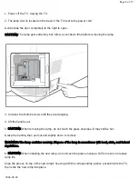
Lamp (0016)
CAUTION: The light source lamp produces extreme heat. Allow a cool-down period before
touching or replacing the lamp assembly.
Note: For protection, the lamp circuit contains a “normally closed” switch. Therefore, the lamp
will not operate with the lamp access door in the open position.
Note: There are no tools required for this procedure.
1.
Slide the lamp access door on the rear of the unit to the right. (Item 0096)
2.
Unscrew the two silver thumbscrews holding the Lamp assembly in place.
3.
Slide the old lamp assembly out by crisping the “metal handle” and pulling straight out.
4.
Install the replacement lamp assembly by pushing into place and tightening the thumbscrews.
5.
Slide the Lamp access door to the left to close
. “The unit will not operate with the back on
and this door open.”
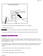
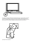
Light Engine
CAUTION: Do not remove the three “SILVER” nuts and washers as these hold the Light Engine
support bracket and are critical adjustment points for focus and picture alignment.
CATUION: The Light Engine has an operating voltage of approximately 1,000 volts. Always use
caution when working in the vicinity of the Light Engine while the unit is in operation.
Note: The LCoS Light Engine comes pre-adjusted. No adjustment for focus should be required.
In rare cases, the set may require a minor focus touch up.
Note: Use care with the routing of the wiring for the Customer Keyboard when replacing the
upper-back. Also, note mounting direction of the Upper-back support bracket for proper
re-installation.
1.
Remove the Lower and Upper Back Covers.
2.
Remove the Cooling System Fan Assembly.
3.
Remove the (3) “BLACK” T-10 Torx screws (Y) (mounted on posts) located in the vicinity of each
of the 3 “silver” nuts and washers.
Note: The front T10 Torx screw is located directly beneath the 10mm wide, white clip, located on
the top front of the Light Engine housing.
4.
Disconnect the wiring harness connected to the Light Engine power supplies, the Main
Power supply, and the video cable coming from the Scaler Panel.
Summary of Contents for 55PL9524/37
Page 10: ...Page 9 of 15 2004 08 09 ...
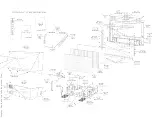
Page 23: ...Display The Main Cabinet Exploded View ...
Page 34: ......
Page 35: ......
Page 36: ......
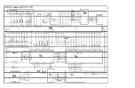
Page 37: ...IIC BUS SIGNAL DIAGRAM ...
Page 39: ......
Page 40: ......
Page 41: ......
Page 42: ......
Page 43: ......
Page 44: ......
Page 45: ......
Page 46: ......
Page 47: ......
Page 48: ......
Page 49: ......
Page 50: ......
Page 51: ......
Page 52: ......
Page 53: ......
Page 54: ......
Page 55: ......
Page 56: ......
Page 57: ......
Page 58: ......
Page 59: ......
Page 60: ......
Page 61: ......
Page 62: ......
Page 63: ......
Page 64: ......
Page 65: ......
Page 66: ......
Page 67: ......
Page 68: ......
Page 69: ......
Page 70: ......
Page 71: ......
Page 72: ......
Page 73: ......
Page 74: ......
Page 75: ......
Page 76: ......
Page 77: ......
Page 78: ......
Page 79: ......
Page 80: ......
Page 81: ......
Page 82: ......
Page 83: ......
Page 84: ......
Page 87: ... W INPUT POWER PANEL Bottom View Return to Circuit Board TOC ...
Page 89: ... U1 MAIN POWER PANEL Bottom View Return to Circuit Board TOC ...
Page 91: ... K SYSTEM BOARD Bottom View Return to Circuit Board TOC ...
Page 92: ...Refer to the next page for Bottom Side View B SSB PANEL Top View Return to Circuit Board TOC ...
Page 93: ... B SSB PANEL Bottom View Return to Circuit Board TOC ...
Page 95: ... SL SCALER PANEL Bottom View Return to Circuit Board TOC ...
Page 97: ... F DW PIP PANEL Bottom View Return to Circuit Board TOC ...
Page 99: ... CB1 3D COMB FILTER PANEL Bottom View Return to Circuit Board TOC ...
Page 101: ... V REAR JACK PANEL Bottom View Return to Circuit Board TOC ...
Page 103: ... O1 SIDE JACK PANEL Bottom View Return to Circuit Board TOC ...
Page 105: ... LS LED SENSOR PANEL Bottom View Return to Circuit Board TOC ...
Page 107: ... P1 LED KEYBOARD PANEL Bottom View Return to Circuit Board TOC ...
Page 109: ... TS1 THERMAL SENSOR PANEL Bottom View Return to Circuit Board TOC ...
Page 111: ... AA1 AUDIO AMPLIFIER PANEL Bottom View Return to Circuit Board TOC ...
Page 112: ...Refer to the next page for Bottom Side View Return to Circuit Board TOC ...
Page 113: ...Return to Circuit Board TOC ...
Page 115: ... 7665 Page 1 P1 P2 P3 P4 P5 P6 P7 C1 C2 C3 C4 C5 C6 F30 F31 F32 L14 L15 L16 V31 ...
Page 116: ... 7665 Page 2 V32 F14 I 6 L 8 V 1 V 2 V 6 V 7 V 8 V 9 V10 L1 L2 L3 L4 L5 L6 L7 L8 L9 ...
Page 117: ... 7665 Page 3 F17 F18 F19 F20 L12 V19 V20 V21 V28 V29 V30 B51 B52 B53 B54 B55 B57 B58 B60 A15 ...
Page 121: ... 7665 Page 7 F2 F14 F15 F16 F17 F18 V19A V20A F 3 F 4 F 5 F 6 F 7 F 8 F 9 F10 F11 F12 F13 A1 ...
Page 122: ... 7665 Page 8 A2 A3 A4 A5 A6 A7 A8 ...
Page 124: ...Overall Cabinet Exploded View Page 1 of 5 ...
Page 125: ...Cabinet Detail 1 Exploded View Page 2 of 5 ...
Page 126: ...Cabinet Detail 2 Exploded View Page 3 of 5 ...
Page 127: ...Power Supply Assembly Exploded View Page 4 of 5 ...


