background image

22

C

ONNECTING

P

ERIPHERAL

E

QUIPMENT

REAR OF TV

4

1

VIDEO RECORDER

CABLE

A/V IN

A/V OUT

3

RF OUT

RF IN

2

5

A/V PERIPHERAL

RF IN

RF OUT

VIDEO

S-VIDEO

L

Pb

Pr

VIDEO

S-VIDEO

L

AUDIO

L

R

AUDIO

L

R

G/Y

R/Pr

B/Pb

V

H

SYNC

L

R

AUDIO

L

R

AUDIO

AV4-480p/1080i-60Hz, 576p-50Hz

AV5-RGB, 480p/1080i-60Hz, 576p-50Hz

INPUT-AV 2

SUBWOOFER

MONITOR

OUT

INPUT-AV 1

Y

AMP SWITCH

CENTER CHANNEL AMP INPUT

ANTENNA IN 75

EXT

INT

+

_

VIDEO

S-VIDEO

L

Pb

Pr

VIDEO

S-VIDEO

L

AUDIO

L

R

AUDIO

L

R

G/Y

R/Pr

B/Pb

V

H

SYNC

L

R

AUDIO

L

R

AUDIO

AV4-480p/1080i-60Hz, 576p-50Hz

AV5-RGB, 480p/1080i-60Hz, 576p-50Hz

INPUT-AV 2

SUBWOOFER

MONITOR

OUT

INPUT-AV 1

Y

AMP SWITCH

CENTER CHANNEL AMP INPUT

ANTENNA IN 75

EXT

INT

+

_

2

1

DVD PLAYER

COMPONENT VIDEO

OUT

A/V OUT

REAR OF TV

VIDEO

S-VIDEO

L

Pb

Pr

VIDEO

S-VIDEO

L

AUDIO

L

R

AUDIO

L

R

G/Y

R/Pr

B/Pb

V

H

SYNC

L

R

AUDIO

L

R

AUDIO

AV4-480p/1080i-60Hz, 576p-50Hz

AV5-RGB, 480p/1080i-60Hz, 576p-50Hz

INPUT-AV 2

SUBWOOFER

MONITOR

OUT

INPUT-AV 1

Y

AMP SWITCH

CENTER CHANNEL AMP INPUT

ANTENNA IN 75

EXT

INT

+

_

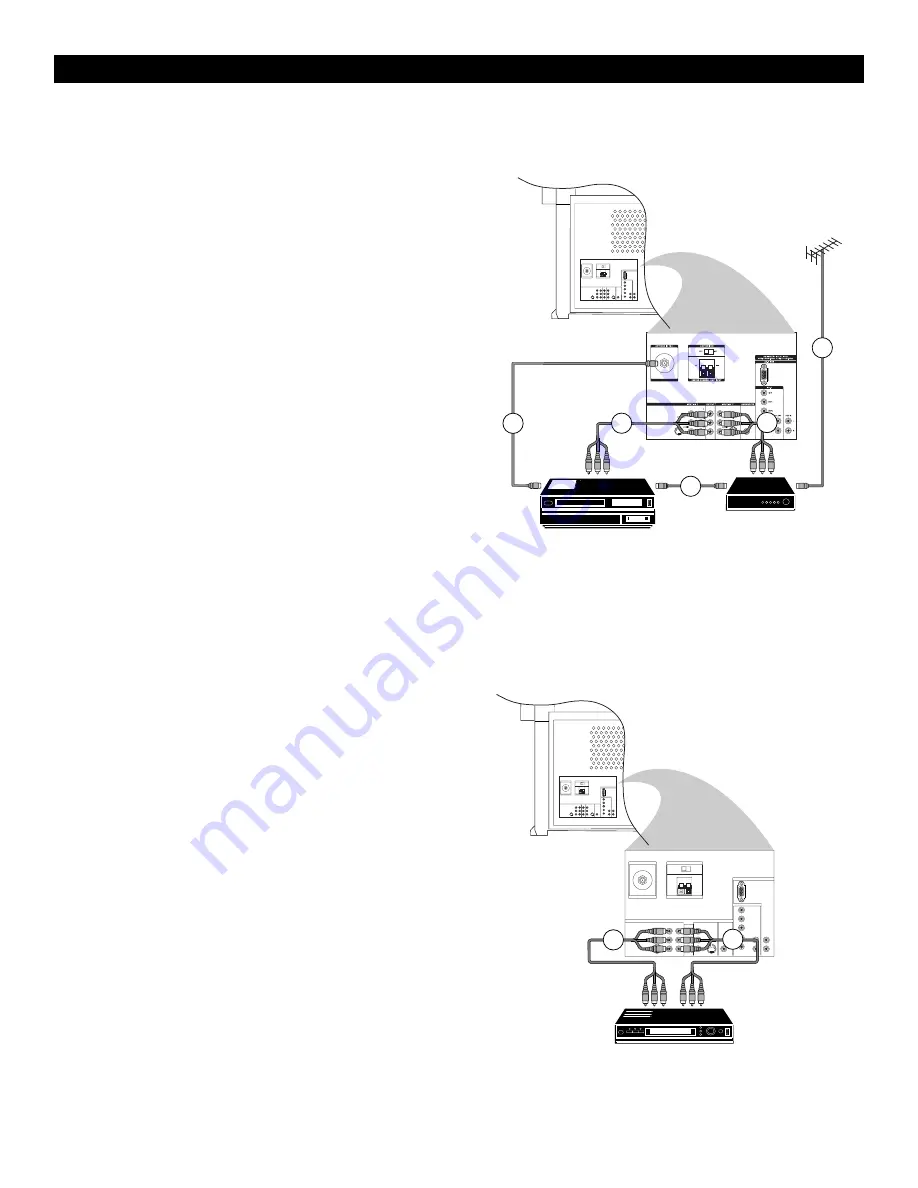
Video Recorder and Other A/V Peripherals

1

Connect the RF cable to the RF socket on your A/V peripheral
equipment.

2

To obtain better picture quality, also connect the Video and Audio
left and Audio right (only for stereo equipment) cables to the
VIDEO and AUDIO L (mono) and AUDIO R input of the INPUT-
AV 2 sockets.

Note : In case of mono equipment, only the left loudspeaker
reproduces sound. Use a mono-to-stereo adapter (not supplied)
for sound reproduction via the internal loudspeakers.

3

Connect the RF output of the A/V peripheral equipment to the RF
input on the video recorder.

4

When a video recorder is not connected to MONITOR OUT on
your TV, you can record a programme only from the aerial or
from the cable system.

Only when a video recorder is connected to MONITOR OUT is it
possible to record a programme from other equipment connected
to the TV. See page 32.

Connect Video and Audio left (mono) and Audio right cables from
the video recorder A/V inputs to the VIDEO and 
AUDIO L (mono) and AUDIO R sockets of the MONITOR OUT
on your TV.

5

Connect from the RF output on the video recorder to the
ANTENNA IN 75

socket on your TV.

DVD Player

Note : Progressive-scan DVD players can be connected to the AV4 or
AV5 inputs only.

1

Connect the cables of your DVD player with component video
output to the Y-Pb-Pr INPUT-AV 1 sockets on your TV.

2

Connect the cables from the Video and Audio (L and R) outputs
on the DVD player to the INPUT-AV 1 VIDEO and AUDIO L
(mono) and R inputs on your TV.

See the handbook for your DVD player.

Note :The names of the component video sockets may differ
depending on the DVD player or digital source equipment used.
For example, besides YPbPr, you may see R-Y/B-Y/Y or CrCbY.
Although abbreviations and terms may vary, the letters B and R
stand for the blue and red color component signal connectors,
respectively.The Y indicates the luminance signal. If necessary, see
the handbook for the digital equipment for more information.

Summary of Contents for 46PW9527

Page 1: ...3135 035 xxxxx Rear projectionTV with HD Input Rear projectionTV with HD Input 46PW9527 51PW9527 ...

Page 2: ...uously a bright white line is displayed across the screen cleaning the TV screen never use abrasive cleaning agents use a slightly damp chamois leather or soft cloth a lightning storm is occurring the set is left unattended for a prolonged period Never attempt to repair a defective TV yourself Always consult a skilled service person Battery Usage CAUTION To prevent battery leakage which may result...

Page 3: ...automatic digital noise reduction and auto sharp ness to provide the best possible picture Automatic Phosphor Aging Compensation APAC functions like a screen saver for your TV Nonmoving images can be bad for a television screen If a video image remains stationary it can eventually leave a permanent after image Video games and the sta tionary black bars around some movies are examples of sources of...

Page 4: ...r local dealer if your main supply is different To prevent damaging the mains AC cord which could cause hazard do not place the TV on the cord 4 Remove the cover of the battery com partment on the remote control Insert the two batteries supplied Type R6 1 5V The batteries supplied do not contain the heavy metals mercury and cadmi um Nevertheless in many countries exhausted batteries may not be dis...

Page 5: ...andset is aimed at it and remote keys are pushed CHANNEL fi fi The fi fi key selects channels in descend ing order The key selects channels in ascending order When using the on screen menu press Channel or fi fi to navigate up and down IntelliSense When pressed automatically adjusts the set s picture convergence using the Auto IntelliSense focus feature STANDBY Switches the TV on or activates standby mo...

Page 6: ... off FREEZE Press to freeze the main picture when PIP is off In teletext mode press to hold a page DYNAMIC NOISE REDUCTION DNR Press to select Off Minimum medium or maximum OK Press to activate or select menu choices CURSOR LEFT Press to navigate the menus and adjust the settings VOLUME Increases or decreases volume DIGITS 0 9 Press to select a channel For Channels with two digits you must press t...

Page 7: ...he menus of accessory devices CC Press to turn Closed captioning On Off or On with Mute MENU ON OFF Press to turn the on screen menu on and off CURSOR UP DOWN RIGHT Press to navigate the menus and adjust the settings CHANNEL Press to select channels in ascending and descending order MUTE Press to mute the sound To restore the sound press the key again Backlight Press to light the volume channel an...

Page 8: ...nt position in the menu hierarchy The puck is always present when the menu system is displayed The puck is divided into 4 parts They correspond to the directional controls up down left right on the remote con trol The arrows on the cursor indicate which directions to choose When menu items cannot can fit on the TV display only a portion is shown Those omitted are indicated by a cluster of Direct s...

Page 9: ... names will always be written in Latin characters even when a language has been selected which uses other characters Automatic Channel installation 1 Select Automatic installation in the Install menu Note All channels must be unlocked in order to autopro gram If requested enter your PIN to unlock all channels See TV Features menu Child lock p 13 2 Press the cursor down The autoprogramming option l...

Page 10: ...rst character and press OK Repeat for every character you want to enter Select Space to enter a space Delete to erase the highlighted character in the name entered Shift to display upper or undercast characters on the keyboard Special to display special characters on the keyboard Press OK to confirm 4 Press the cursor left repeatedly when you have fin ished naming the selected channel or periphera...

Page 11: ... er reduction without motion compensation Pixel Plus creates near High Definition performance inside the TV on the basis of a regular input signal The number of lines are increased and the number of pix els on a line are doubled in combination with Digital Natural Motion As such Pixel Plus enhances both regular broadcast signals and DVD or Digital TV input towards unparalleled sharpness and depth ...

Page 12: ...r sor left right Remember control settings are at normal mid range levels when the bar scale is centred Note Smart Sound allows you to select from a list a preset sound settings Dual X is only available with dual sound transmission Mono Stereo is only selectable in case of analogue stereo trans mission Nicam Analogue is only selectable in case of Nicam transmis sion AVL Automatic Volume Leveller A...

Page 13: ...emote control Child lock 1 Select Child lock with the cursor down 2 Press the cursor right to enter the Child lock menu Enter the access code Note You have to re enter your code each time you enter the child lock menu Important If you have forgotten your code Select Cancel with the cursor down Select Set Change code in the Setup menu See General menu Set Change code p 13 Press OK Press the cursor ...

Page 14: ... channel surf list or a previous channel toggle Dual Screen Format sets the PIP button b to display a dual screen or a number of PIP windows Freeze format sets which type of default Freeze option you want to appear when you press the Freeze button S Factory Settings resets the picture and sound settings to the factory defaults OSD sets the size of the volume and channel display Programme title set...

Page 15: ...screen How well these light sources align is called Convergence Convergence can get misaligned You can tell by the appearance of halos around the objects in the picture You can either set the convergence manually or have the TV do it automatically 1 Press the MENU Ï key on the remote control to summon the main menu 2 Press the cursor down to select Setup 3 Press the cursor right to select Converge...

Page 16: ...t all the features sequentially in a loop Press one of the cursor keys to stop the Auto demo If one of the features has been selected this particu lar feature demo will run one time only until activat ed again and the Demo menu will reappear Select Dealer Demo Select Digital options Light sensor and Comb filter On or Off to really see the difference in picture quality In Dealer Demo mode it is pos...

Page 17: ...ess and hold the b key choose another PIP size Switching Screens Press the c button to swap the main screen and the auxiliary screen Changing PIP Channels Use the cursor to select the PIP window and change channels normally Moving the PIP screen When a single PIP format is selected press the OK but ton to make the PIP screen movable Press the cursor up down left right to move the PIP screen in the...

Page 18: ...ent Use the INPUT AV 1 L eft and R ight AUDIO sockets for sound con nections 3 S VIDEO super video sockets compatible with 480i and 576i signals Use to connect peripherals having Super VHS S VHS outputs such as VCRs DVD players laser disc players video game players satellite receivers or other equipment 4 VIDEO composite sockets INPUT AV 1 INPUT AV 2 and TV s side socket panel AV3 compatible with ...

Page 19: ...connections Use the AV4 L eft and R ight AUDIO sockets for sound connections See the handbook for the device you are connecting 2 AV4 use to connect digital equipment with a 1080i 480p 60Hz or 576p 50Hz signal output such as digital set top boxes or DVD players The AV5 socket accepts a DB15 connector Note however that adaptors can also be used to connect from compo nent video output to this DB15 s...

Page 20: ...ting the video recorder to the VIDEO input See the handbook for the video recorder IfYou Do Not Make theVideo and Audio Connections in Step 3 Above Search for and store the test signal of the video recorder 1 Unplug the RF cable from the RF socket of your video recorder 2 Switch on your TV and put the video recorder on the test signal or play a prerecorded tape See the handbook for your video reco...

Page 21: ... your TV does not disturb recording Recording a Programme onYourVideo Recorder Connected to MONITOR OUT from Audio Video Equipment Connected to AV1 AV2 or to the Sockets on the Side of theTV AV3 1 Switch on the equipment 2 Select the correct external source on your TV and on your video recorder 3 Set your video recorder to record You record what you are watching on the screen Do not switch channel...

Page 22: ...er reproduces sound Use a mono to stereo adapter not supplied for sound reproduction via the internal loudspeakers 3 Connect the RF output of the A V peripheral equipment to the RF input on the video recorder 4 When a video recorder is not connected to MONITOR OUT on your TV you can record a programme only from the aerial or from the cable system Only when a video recorder is connected to MONITOR ...

Page 23: ... or with RGB output phono type connectors to the AV3 inputs for video and audio left and right Also connect to the H and V SYNC inputs on the TV if required for your digital equipment Note The AV3 sockets are compatible with some digital equipment hav ing RGB outputs with sync on green or RGB with separate H and V sync Output standards for digital equipment however may vary by man ufacturer No ind...

Page 24: ...DEO cable with the S VIDEO socket instead of making a connection to the VIDEO socket 2 Connect the equipment to the AUDIO L socket for mono or both the AUDIO L and R for stereo Headphone 1 Insert the plug into the headphone socket at the right side of the TV 2 Press H on the remote control to switch off the internal loud speakers of the TV Notes The headphone impedance must be between 8 and 4000 O...

Page 25: ...ires from the surround sound amplifier s front and surround sound speaker sockets to the front and surround sound speakers 4 Connect an audio cable from the SUBWOOFER output of the TV to the Low Level Input sockets on the powered subwoofer 5 Adjust volume for the surround sound amplifier and powered sub woofer at those pieces of equipment 1 3 3 4 AMPLIFIER POWERED SUBWOOFER 2 REAR OF TV VIDEO S VI...

Page 26: ...ssory buttons to control an accessory device with the remote control You can control a TV CBL VCR or Amplifier by pressing the button once A green indicator lights up When you press the button again for 1 second you can control a HD SAT DVD or CD A red indicator lights up To return to TV mode press the TV button TV Channels Enter the channel number of the TV channel you want to watch with the digi...

Page 27: ...bright over the entire screen PLACEMENT OF THE TV See page 4 CLEANING To avoid possible shock hazard be sure the TV is unplugged from the electrical outlet before cleaning Regularly dust the TV with a dry nonscratching duster to keep the TV clean When cleaning the TV take care not to scratch or damage the screen surface Avoid wearing jewelry or using anything abrasive Do not use household cleaners...

Page 28: ...onnections correctly If you have connected digital equipment to the AV4 or AV5 sockets check the colour space setting on the equipment or TV and change the setting on either if necessary Check to be sure the TV is not placed too near speakers or magnetic objects Adjust the TV s convergence Horizontal dotted lines This may be caused by electrical interference from appliances such as hair dryers or ...

Page 29: ...VD 22 f favorite channel list 10 features menu 13 freeze 6 g general menu 14 give name 10 h headphone 33 HD inputs 10 i information on screen i key 6 intellisense 5 15 m manual installation 9 menu use 8 p picture menu 11 pip 17 r remote control 6 7 s s video 18 23 sound menu 12 source menu 15 t troubleshooting before calling service 28 v video recorder 20 volume 5 y ypbpr 18 ...

Page 30: ...0Hz 10 kHz at 5 THD flat response 8 ohm load Bass Boost Center channel input Subwoofer out Ease of Use Smart Picture five modes Smart Sound four modes Dual language onscreen display and menu control Sleeptimer and Timer Childlock 100 presets Favorite Programme List Remote control Connectivity Rear MONITOR OUT CVBS and audio L R INPUT AV 1 CVBS S Video and audio L R Component video input CVI YPbPr ...

Page 31: ...s as a consumer In the event of difficulty please contact the Philips Information Centre in any country see enclosed addresses CONDICIONES DE GARANTIAS INTERNATIONALES Philips garantiza este producto durante 1 año a partir de la fecha de adquisición contra defectos debidos a una imper fecta fabricación o malos materiales Esta garantía cubre tanto las piezas de recambio como la mano de obra Las rep...

Page 32: ... Philips Electronics Ireland Ltd Newstead Clonskeagh Dublin 14 Phone 01 7640000 Fax 01 7640175 ITALY Philips S P A Servicio Consumatori Philips Piazza IV Novembre 3 I 20124 Milano Phone 167 820026 linea verde Fax 02 67522660 LUXEMBURG Philips Luxemburg S A 19 21 rte d Arlon L 8001 Strassen Phone 44 38 38 1 Fax 45 39 88 the NETHERLANDS Philips Consumenten Belangen Antwoordnummer 500 NL 5600VB Eindh...

Page 33: ...RGENTINA Philips Argentina S A Centro de Información al Usarío Vedia 3892 1430 Buenos Aires Phone 01 5442047 Fax 01 5452928 BRASIL Philips da Amazona Indústria Electrônica Ltda Rua Jacerú 151 Brooklin 04705 000 Sao Paulo SP Phone 800123123 Fax 011 5315973 CHILI Philips Chilena S A Avenida Santa Maria 0760 P O Box 2687 Santiago de Chile Phone 02 730 2000 Fax 02 777 6730 COLOMBIA Industrias Philips ...

Page 34: ... 021 4726839 Fax 021 4726843 Philips Authorized Service Centre 801 Dong Feng Road East Guangzhou 510080 Phone 020 7766990 Fax 020 7766990 Philips Authorized Service Centre Bejing Jing Pu Elec Service Station 6 F Guo Hu Department Store Xan Wu Men West Street Bejing 100053 Phone 01 3021589 Fax 01 3021589 Philips Authorized Service Centre 148 Fu Jian Road M Shanghai 200001 Phone 021 3281005 38275 Fa...

Page 35: ...44 PHILIPPINES Philips Electronics and Lighting Inc 106 Valero St Salcedo Village Makati Metro Manilla Phone 02 8100161 Fax 02 8173474 SINGAPORE Philips Singapore Private Ltd Consumer Service Dept Lorong 1 Toa Payoh P O Box 340 Singapore 319762 Phone 3502000 Fax 2508037 TAIWAN Philips Taiwan Ltd Consumer Products Division 4F 1 5 Lane 768 Pateh Rd Sec 4 P O Box 22978 Taipei Phone 02 7882856 Fax 02 ...

Page 36: ...36 ...

Reviews: