IC Data Sheets
8.
8.4
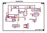
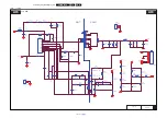
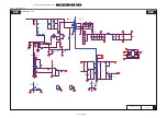
Diagram
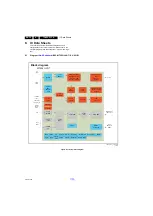
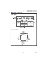
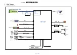
B09, MxL661 (IC U104)
Figure 8-6 Internal block diagram and pin configuration
19760_301.eps
Block diagram
Pinning information
24
23
22
21
20
19
18
17
16
15
14
13
7
8
9
10
11
12
1
2
3
4
5
6
LNA_INP
LNA_INN
AS
GND_
X
TAL
CLK_OUT
XTAL_
P
XTAL_
N
VDD_1p
8
VDD_IO
AGC_1
AGC_2/GPO_3
MxL661
VDD_3p3
RESET_N
VD
D_1p
8
VDD_1p8
GND_DIG
VDD_1p2
IF
_OUT
N_
1
IF_OUTP_1
IF
_O
UTP_2/
GPO
_
1
IF_OUT
N_2
/GPO_
2
SDA
SCL
VD
D_3p
3
Crystal
Reference
I
2
C
Voltage
Regulator
AGC1
RF
Synth
Gain
Control
IF
Synth
Synth
Calibration
LNA
AGC2
Channel
Filtering
CLK_OUT
IF1 Out
IF2 Out
RF Input
Balun


