background image

Service Modes, Error Codes, and Fault Finding

EN 23

L12M3.1L LA

5.

2013-Jun-21

After entering SAM, the following items are displayed, with 
“SAM” in the upper right corner of the screen to indicate that the 
television is in Service Alignment Mode.

Menu items and explanation:
1.

System Information.

Op Hour:

 This represents the life timer. The timer 

counts normal operation hours, but does not count 
Stand-by hours.

MAIN SW ID:

 See paragraph 

 Software Identification, 

Version, and Cluster

 for the SW name definition. 

ERR:

 Shows all errors detected since the last time the 

buffer was erased. Five errors possible.

OP1/OP2:

 Used to read-out the option bytes. See 

paragraph 

6.4 Option Settings

 in the Alignments 

section for a detailed description. Ten codes are 
possible.

2.

Clear.

 Erases the contents of the error buffer. Select this 

menu item and press the MENU RIGHT key on the remote 
control. The content of the error buffer is cleared.

3.

Options.

 To set the option bits. See paragraph 

6.4 Option 

Settings 

in the “Alignments” chapter for a detailed 

description.

4.

Alignments.

RGB Align.

 To align the White Tone. See 

 White Tone 

Alignment: 

 for a detailed description.

Ambilight.

 To align the Ambilight Units.

5.

NVM editor.

NVM Editor.

 To change the NVM data in the television 

set. See also paragraph 

5.6 Fault Finding and Repair 

Tips

.

Service Data.

 12 nc data.

6.

Upload to USB.

7.

Download from USB.

8.

Initialise NVM.

 To initialize a (corrupted) NVM. Be careful, 

this will erase all settings!

9.

Dealer Options.

10.

Event Count. 

Hardware Events.

 To Display and Clear the hardware 

events.

Software Events.

 To Display and Clear the software 

events.

11.

RF4CE Pairing Tables.

 To Clear the paired remote 

immediately.

How to Navigate

In the SAM menu, select menu items with the UP/DOWN 
keys on the remote control transmitter. The selected item 
will be indicated. When not all menu items fit on the screen, 
use the UP/DOWN keys to display the next / previous 
menu items.

With the LEFT/RIGHT keys, it is possible to:

Activate the selected menu item.

Change the value of the selected menu item.

Activate the selected sub menu.

When you press the MENU button twice while in top level 
SAM, the set will switch to the normal user menu (with the 
SAM mode still active in the background). To return to the 
SAM menu press the MENU button.

The “INFO[i+]/OK” key from the user remote will toggle the 
OSD “on/off” with “SAM” OSD remaining always “on”.

Press the following key sequence on the remote control 
transmitter: “

062596

” directly followed by the 

MENU

 button 

to switch to SDM (do not allow the display to time out 
between entries while keying the sequence).

How to Store SAM Settings

To store the settings changed in SAM mode (except the 
OPTIONS and RGB ALIGN settings), leave the top level SAM 
menu by using the POWER button on the remote control 
transmitter or the television set. The mentioned exceptions 
must be stored separately via the STORE button.

How to Exit

Switch the set to STANDBY by pressing the mains button on 
the remote control transmitter or the television set, or by 
keying-in the “00” sequence on a standard RC-transmitter.

Note:

When the TV is switched “off” by a power interrupt while in 
SAM, the TV will show up in “normal operation mode” as 
soon as the power is supplied again. The error buffer will 
not be cleared.

In case the set is in Factory mode by accident (with “F” 
displayed on screen), pressing and holding “VOL-“ button 
for 5 seconds and then followed by pressing and holding 
the “CH-” button for another 5 seconds should exit the 
Factory mode.

5.2.4

Customer Service Mode (CSM)

Purpose

The Customer Service Mode shows error codes and 
information on the TV’s operation settings. A call centre can 
instruct the customer (by telephone) to enter CSM in order to 
identify the status of the set. This helps them to diagnose 
problems and failures in the TV before making a service call.
The CSM is a read-only mode; therefore, modifications are not 
possible in this mode.

Specifications

Ignore “Service unfriendly modes”.

Set volume to 25%.

Set Smart Picture to “Game”.

Set Smart Sound to “Standard”.

Line number for every line (to make CSM language 
independent).

Set the screen mode to full screen (all contents on screen 
is visible).

After leaving the Customer Service Mode, the original 
settings are restored.

Possibility to use “CH+” or “CH-” for channel surfing, or 
enter the specific channel number on the RC.

How to Activate

To activate CSM, press the following key sequence on a 
standard remote control transmitter: “

123654

” (do not allow the 

display to time out between entries while keying the sequence).
 
After entering the Customer Service Mode, the following items 
are displayed:

Menu Explanation CSM1

1.

Set Type.

 Type number, e.g. 39PFL4508G/78. (*)

2.

Production code.

 Product serial no., e.g. 

BZ1A1008123456 (*). BZ= Production centre, 1= BOM 
code, A= Service version change code, 10= Production 
year, 08= Production week, 123456= Serial number.

3.

Installation date.

 Indicates the date of the first initialization 

of the TV. This date is acquired via time extraction.

4.

a - Option Code 1.

 Option code information (group 1).

b - Option Code 2.

 Option code information (group 2).

5.

SSB.

 Indication of the SSB factory ID (= 12nc). (*)

6.

Display. 

Indication of the display ID (=12 nc). (*)

7.

PSU

. Indication of the PSU factory ID (= 12nc).

8.

RF4CE

. Indication of the RF4CE software version 

(= 12nc).

(*)

 If an NVM IC is replaced or initialized, these items must be 

re-written to it. ComPair will foresee in a possibility to do this. 
Also the NVM editor in the SAM menu can be used.

Menu Explanation CSM2

1.

Current Main SW.

 Shows the main software version.

2.

Standby SW.

 Shows the Stand-by software version.

3.

Panel Code.

 Shows the current display code.

Summary of Contents for 32PFL3518G/77

Page 1: ...ring Diagram 39 4500 series 42 Wiring Diagram 42 3500 series 43 Wiring Diagram 42 46 5000 5500 series 45 Wiring Diagram 46 4500 series 46 Wiring Diagram 47 7000 series 47 Wiring Diagram 47 8000 series 48 Wiring Diagram 55 7000 series 49 Wiring Diagram 55 8000 series 50 Block Diagram 3139 123 65451 51 Block Diagram 3139 123 65441 52 10 Circuit Diagrams and PWB Layouts A 715G5778 PSU 53 55 56 A 715G...

Page 2: ... Option Board J Sensor Board E Keyboard Leading Edge AL AmbiLight Sheet 32PFL3508G 78 2 3 4 1 4 3 7 1 9 1 9 13 10 3 10 6 10 10 10 8 11 1 32PFL3518G 77 2 3 4 1 4 3 7 1 9 1 9 13 10 3 10 6 10 10 10 8 11 1 32PFL3518G 78 2 3 4 1 4 3 7 1 9 1 9 13 10 3 10 6 10 10 10 8 11 1 32PFL4508G 77 2 3 4 2 4 3 7 1 9 2 9 13 10 3 10 6 10 9 10 8 11 2 39PFL3508G 78 2 3 4 3 4 3 7 1 9 3 9 13 10 2 10 6 10 4 10 10 10 8 11 3...

Page 3: ...al Video Digital Audio In Figure 2 3 HDMI type A connector 1 D2 Data channel j 2 Shield Gnd H 3 D2 Data channel j 4 D1 Data channel j 5 Shield Gnd H 6 D1 Data channel j 7 D0 Data channel j Rear HDMI 1 HDMI 2 ARC ANTENNA AUDIO IN DVI VGA SPDIF OUT CVBS Y Pb Pr L R SERV U VGA Side HDMI USB 1 USB 2 NETWORK 19510_001_130424 eps 130424 3 3 9 11 12 10 1 2 4 5 7 8 6 Rear HDMI 1 HDMI 2 HDMI 3 AUDIO IN DVI...

Page 4: ...j 8 Shield Gnd H 9 D0 Data channel j 10 CLK Data channel j 11 Shield Gnd H 12 CLK Data channel j 13 Easylink Control channel CEC jk 14 n c 15 DDC_SCL DDC clock j 16 DDC_SDA DDC data jk 17 Ground Gnd H 18 5V j 19 HPD Hot Plug Detect j 20 Ground Gnd H 6 VGA Video RGB In Figure 2 7 VGA Connector 1 Video Red 0 7 VPP 75 j 2 Video Green 0 7 VPP 75 j 3 Video Blue 0 7 VPP 75 j 4 n c 5 Ground Gnd H 6 Groun...

Page 5: ...Technical Specifications and Connections EN 5 L12M3 1L LA 2 2013 Jun 21 11 Cinch S PDIF Out Bk Coaxial 0 4 0 6VPP 75 ohm kq 12 Aerial In F type Coax 75 D ...

Page 6: ... supply section both in normal operation G and in stand by F These values are indicated by means of the appropriate symbols 3 3 2 Schematic Notes All resistor values are in ohms and the value multiplier is often used to indicate the decimal point location e g 2K2 indicates 2 2 k Resistor values with no multiplier may be indicated with either an E or an R e g 220E or 220R indicates 220 All capacito...

Page 7: ...s easy to do and is a good service precaution 3 4 Abbreviation List 0 6 12 SCART switch control signal on A V board 0 loop through AUX to TV 6 play 16 9 format 12 play 4 3 format AARA Automatic Aspect Ratio Adaptation algorithm that adapts aspect ratio to remove horizontal black bars keeps the original aspect ratio ACI Automatic Channel Installation algorithm that installs TV channels directly fro...

Page 8: ...roadcast grade video Uncompressed digital component or digital composite signals can be used The SDI signal is self synchronizing uses 8 bit or 10 bit data words and has a maximum data rate of 270 Mbit s with a minimum bandwidth of 135 MHz iTV Institutional TeleVision TV sets for hotels hospitals etc LS Last Status The settings last chosen by the customer and read and stored in RAM or in the NVM T...

Page 9: ...rd Definition SDA Serial Data I2C SDA F DAta Signal on Fast I2C bus SDI Serial Digital Interface see ITU 656 SDRAM Synchronous DRAM SECAM SEequence Couleur Avec Mémoire Colour system mainly used in France and East Europe Colour carriers 4 406250 MHz and 4 250000 MHz SIF Sound Intermediate Frequency SMPS Switched Mode Power Supply SoC System on Chip SOG Sync On Green SOPS Self Oscillating Power Sup...

Page 10: ...of this chapter 4 1 Cable Dressing 4 2 Service Positions 4 3 Assy Panel Removal 4 4 Set Re assembly Notes Figures below can deviate slightly from the actual situation due to the different set executions 4 1 Cable Dressing Figure 4 1 Cable dressing 32 35xx series 19511_004_130614 eps 130614 ...

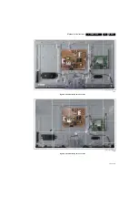
Page 11: ...Mechanical Instructions EN 11 L12M3 1L LA 4 2013 Jun 21 Figure 4 2 Cable dressing 32 45xx series Figure 4 3 Cable dressing 39 35xx series 19511_005_130614 eps 130614 19511_007_130617 eps 130617 ...

Page 12: ...Mechanical Instructions EN 12 L12M3 1L LA 4 2013 Jun 21 Figure 4 4 Cable dressing 39 45xx series Figure 4 5 Cable dressing 42 35xx series 19510_100_130424 eps 130424 19510_101_130424 eps 130424 ...

Page 13: ...Mechanical Instructions EN 13 L12M3 1L LA 4 2013 Jun 21 Figure 4 6 Cable dressing 42 45xx series Figure 4 7 Cable dressing 42 5xxx series 19511_008_130617 eps 130617 19510_102_130424 eps 130424 ...

Page 14: ...nical Instructions EN 14 L12M3 1L LA 4 2013 Jun 21 Figure 4 8 Cable dressing 46 45xx series Figure 4 9 Cable dressing 46 55xx series 19510_103_130424 eps 130425 10000_035_090121 eps 100416 Not yet available ...

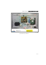
Page 15: ...tructions EN 15 L12M3 1L LA 4 2013 Jun 21 Figure 4 10 Cable dressing 47 70xx series 19511_009_130617 eps 130617 100 m m 11 150 m m 1 Note keep out area ensure no cable dressings are allowed within the red marked area ...

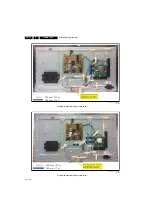
Page 16: ...re 4 12 Cable dressing 55 70xx series 19511_010_130617 eps 130617 100 m m 11 150 m m 1 Note keep out area ensure no cable dressings are allowed within the red marked area 19511_011_130617 eps 130617 100 m m 13 150 m m 1 Note keep out area ensure no cable dressings are allowed within the red marked area ...

Page 17: ...tructions EN 17 L12M3 1L LA 4 2013 Jun 21 Figure 4 13 Cable dressing 55 80xx series 19511_012_130617 eps 130617 100 m m 13 150 m m 1 Note keep out area ensure no cable dressings are allowed within the red marked area ...

Page 18: ...bilight units Ambilight sets in the 5x00 range are equipped with a hatch to disconnect the Ambilight units These hatches are indicated on the rear cover with SERVICE h It is mandatory to open the hatches and disconnect the cables prior to removal of the rear cover 1 For sets in the 5x000 range equipped with Ambilight open the hatch that covers the Ambilight connector and unplug the connector see F...

Page 19: ... the rear cover and will self destruct upon removal Attention it is of the utmost importance to remove all remains of any adhesive that might be left on the inside of the rear cover prior to affixing the new Ambilight units The new units come with double sided adhesive tape Ensure a correct mounting to avoid uneven light emission of the units Refer to Figure 4 18 for the wiring position 19510_106_...

Page 20: ...nd 8000 range it is of the utmost importance to keep cables out of the swivel range when re assembling the set to avoid future cable cut Refer to Figure 4 10 to Figure 4 13 Notes While re assembling make sure that all cables are placed and connected in their original position Pay special attention not to damage the EMC foams in the set Ensure that EMC foams are mounted correctly 19510_107_130424 e...

Page 21: ...Pair has to be connected to the TV set via the ComPair connector which will be accessible through the rear of the set without removing the rear cover In this chassis the set has to be put in Service Mode SDM SDA before you can use ComPair 5 2 1 General Next items are applicable to all Service Modes or are general Life Timer During the life time cycle of the TV set a timer is kept called Op Hour It...

Page 22: ...OP Used to read out the option bytes Ten codes in two rows are possible How to Navigate As this mode is read only there is not much to navigate To switch to other modes use one of the following methods Command MENU from the user remote will enter the normal user menu brightness contrast color etc with SDM OSD remaining and pressing MENU key again will return to the last status of SDM again To prev...

Page 23: ...ave the top level SAM menu by using the POWER button on the remote control transmitter or the television set The mentioned exceptions must be stored separately via the STORE button How to Exit Switch the set to STANDBY by pressing the mains button on the remote control transmitter or the television set or by keying in the 00 sequence on a standard RC transmitter Note When the TV is switched off by...

Page 24: ...ws based fault finding program and an interface box between PC and the defective product The new ComPair II interface box is connected to the PC via an USB cable For the TV chassis the ComPair interface box and the TV communicate via a bi directional cable via the service connector s How to Connect This is described in the ComPair chassis fault finding database Figure 5 3 ComPair II interface conn...

Page 25: ...t blinks 5 5 2 Displaying the Entire Error Buffer Additionally the entire error buffer is displayed when Service Mode SDM is entered 5 6 Fault Finding and Repair Tips Notes It is assumed that the components are mounted correctly with correct values and no bad solder joints Before any fault finding actions check if the correct options are set 5 6 1 NVM Editor In some cases it can be convenient if o...

Page 26: ...er pins 7 8 if not tuner may be faulty Check whether picture is present in CVBS in not check Video section 5 6 12 Front end no picture in digital RF mode Check following points Tuner supply voltage 3V3 presence available at pin 2 4 7216 and F203 I2 C lines are working correctly 3V3 Manually store a known channel and check if there is IF output at tuner pins 2 3 if not tuner may be faulty Supply vo...

Page 27: ... normal conditions so when there is no major problem with the TV the main software and the default software upgrade application can be upgraded with the autorun upg FUS part in the one zip file This can also be done by the consumers themselves but they will have to get their software from the commercial Philips website or via the Software Update Assistant in the user menu see DFU The Autorun upg f...

Page 28: ...B_T2U BIN this takes a couple of seconds Write Channel List Data to TV 1 First ensure via a PC that the filename on the USB stick has the correct format L12M31L_CHTB_U2T BIN 2 Insert the USB stick into the USB slot while in SAM mode 3 Execute the command Channel list Copy from USB to copy the USB data to the TV this takes about a minute to complete Important The file must be located in the Repair ...

Page 29: ...100 white screen as input signal and set the following values Red BL Offset and Green BL Offset to 7 if present All White point values initial to 127 In case you have a color analyzer Measure with a calibrated phosphor independent color analyzer e g Minolta CA 210 in the centre of the screen Consequently the measurement needs to be done in a dark environment Adjust the correct x y coordinates whil...

Page 30: ...l diagnosis possible the microprocessor has to know which ICs to address The presence absence of these specific ICs or functions is made known by the option codes Notes After changing the option s save them with the STORE command Value Cool t b d K Normal t b d K Warm t b d K x t b d t b d t b d y t b d t b d t b d Colour Temp R G B Cool 219 238 255 Normal 253 253 247 Warm 255 226 171 Colour Temp ...

Page 31: ... Overview Table 6 23 Display code overview 6 5 Cable Position Numbers In this chassis the cable position numbers can be defined via the rule that the number is always starting with an E followed by the connector number of the current sourcing board The order is always seen from where the power initiates from So from PSU to SSB from SSB to IR LED panel from IR LED panel to keyboard control panel Fo...

Page 32: ...on 7 1 Introduction The L12M3 1L LA chassis is a digital chassis using a Mediatek chipset It covers screen sizes of 32 to 55 Main key components are the Mediatek MT5396 integrated System On Chip SoC that supports multimedia video audio input System SoC is based on MT5396 NAND Flash 512 Mbyte Hynix DDR 1 33 GHz 512 256 Mbyte Hynix Tuner Frontend configuration Sony Silicon In Can Tuner SUT RA214Z So...

Page 33: ...Circuit Descriptions EN 33 L12M3 1L LA 7 2013 Jun 21 Figure 7 2 SSB key component overview 7000 8000 series 19510_201_130424 eps 130424 ...

Page 34: ...d logic ICs 8 1 Diagram 10 6 2 B02A Tuner demodulator Type SUT RA214 IC1201 Figure 8 1 Internal block diagram and pin configuration 19300_043_120416 eps 120416 Block diagram IQ Gen Image Rejection PLL AGC Terr In Balun FIL 1KΩ 100Ω 1KΩ 10 11 7 8 9 2 3 100Ω 4 1 100Ω I2C 100Ω IQ Gen Image Rejection PLL 3 3 V AGC Terr In Balun FIL 1KΩ 100Ω 1KΩ 10 Tuner I2C SDA SCL IFOUT2 IFOUT1 AGC2 AGC1 11 7 8 9 2 3...

Page 35: ...30 32 33 34 35 XTALI 31 XTALO 48 49 OSCMODE 25 26 27 36 XVSS 13 14 15 16 17 18 19 20 21 22 23 24 VSS TSDATA7 DVDD SCL SDA CVDD TSDATA6 VSS TESTMODE SLVADR0 XVDD PVDD CVDD VSS PVSS VSS TAINM TAINP TAVDD 2 1 GPIO0 GPIO2 TSSYNC TSVALID TSCLK VSS VSS DVDD TSDATA0 TSDATA1 CVDD TSDATA2 TAVSS Oscillator Host I2 C GPIO TTUSDA TTUSCL Terrestrial Tuner TIFAGC TAINP TAINM TSCLK TSSYNC TSVALID TSDATA 7 0 ADC ...

Page 36: ...IC Data Sheets EN 36 L12M3 1L LA 8 2013 Jun 21 8 3 Diagram 10 6 4 B04A MTK5396 power Type MT5396 IC7300 Figure 8 3 Internal block diagram 19300_040_120416 eps 120416 Block diagram MT5396JDNJ ...

Page 37: ...DRV DDRV DVSS VCCK DVSS DVSS DVSS DVSS DVSS V BRDQS2 BRDQS2 BRCLK1 BRCLK1 DDRV DDRV RVREF_ D VCCK DVSS DVSS DVSS DVSS DVSS W BRDQS3 BRDQS3 DVSS DVSS DVSS DVSS VCCK DVSS DVSS DVSS DVSS DVSS Y BRDQM2 BRDQ30 BRDQ28 DVSS DVSS DVSS DVSS DVSS VCCK DVSS DVSS DVSS DVSS DVSS AA BRDQ24 BRDQ26 DVSS DVSS VCCK DVSS DVSS DVSS DVSS DVSS AB BRDQ21 BRDQ23 BRDQ19 BRDQ17 DVSS DVSS VCCK DVSS DVSS DVSS DVSS DVSS AC DD...

Page 38: ...PCIE11_ RXP Y DVSS DVSS DVSS VCCK AVDD12_ HDMI_0_ RX AVDD33_ HDMI_1_ RX HDMI_C EC HDMI_2_ RX_1B HDMI_2_ RX_1 HDMI_2_ RX_2B HDMI_2_ RX_2 AA DVSS DVSS DVSS DVSS AVDD12_ HDMI_3_ RX AVDD33_ HDMI_0_ RX AVSS33_ HDMI_R X HDMI_2_ SDA HDMI_2_ RX_0B HDMI_2_ RX_0 AB VCCK VCCK VCCK VCCK VCCK AVDD33_ HDMI_3_ RX HDMI_2_ PWR5V HDMI_2_ HPD HDMI_2_ SCL HDMI_1_ RX_2B HDMI_1_ RX_2 HDMI_2_ RX_CB HDMI_2_ RX_C AC AVDD3...

Page 39: ...about cable position numbers KEYBOARD CONTROL 1057 E LOUDSPEAKER LOUDSPEAKER 1185 1185 LOUDSPEAKER 1185 LOUDSPEAKER LOUDSPEAKER 1185 1185 LOUDSPEAKER 1185 SSB 1053 L N CN9901 MAIN POWER SUPPLY 1054 A USB2 USB1 NETWORK TV ANTENNA DIGITAL AUDIO OUT L R CVBS Y Pb Pr AUDIO IN DVI HDMI HDM2 1 ARC VGA SERV U OPTION BOARD 1058 O TO PANEL CN401 13P 38P CN408 38P CN408 12P 5P J IR LED BOARD 1056 CN2 3P CN0...

Page 40: ...LOUDSPEAKER 1185 SSB 1053 L N CN9901 MAIN POWER SUPPLY 1054 A B USB2 USB1 NETWORK TV ANTENNA DIGITAL AUDIO OUT L R CVBS Y Pb Pr AUDIO IN DVI HDMI HDM2 HDM 1 ARC VGA SERV U WIFI MODULE WiFi01 OPTION BOARD 1058 O TO PANEL CN401 13P 38P CN408 CN016 5P CN1 11P CN2 3P 38P 6P 12P 5P 13P 4P WiFi Antenna CN8101 TO PANEL CN9101 CN8102 CN8103 CN408 38P CN408 38P CN408 J3 Board Level Repair Component Level R...

Page 41: ...ble position numbers KEYBOARD CONTROL 1057 E LOUDSPEAKER LOUDSPEAKER 1185 1185 J LOUDSPEAKER 1185 LOUDSPEAKER LOUDSPEAKER 1185 1185 LOUDSPEAKER 1185 CN016 5P IR LED BOARD 1056 11P CN2 3P CN1 SSB 1053 L N CN9901 MAIN POWER SUPPLY 1054 A USB2 USB1 NETWORK TV ANTENNA DIGITAL AUDIO OUT L R CVBS Y Pb Pr AUDIO IN DVI HDMI1 ARC VGA SERV U OPTION BOARD 1058 O TO PANEL CN401 13P 38P CN408 38P 5P 13P TO PAN...

Page 42: ...53 See note in Chapter 7 about cable position numbers L N CN9901 MAIN POWER SUPPLY 1054 A B USB2 USB1 NETWORK TV ANTENNA DIGITAL AUDIO OUT L R CVBS Y Pb Pr AUDIO IN DVI HDMI HDM2 1 ARC VGA SERV U WIFI MODULE OPTION BOARD 1058 ALC TO PANEL WiFi Antenna 1G51 51P 11P 1C20 CN016 5P CN201 6P 4P 1D01 17P 1M89 5P WIFI01 6P 1C31 TO PANEL 12P CN8501 5P CN8103 13P CN9101 4P CN8102 LOUDSPEAKER LOUDSPEAKER 11...

Page 43: ...e in Chapter 6 about cable position numbers KEYBOARD CONTROL 1057 E LOUDSPEAKER LOUDSPEAKER 1185 1185 J LOUDSPEAKER 1185 LOUDSPEAKER LOUDSPEAKER 1185 1185 LOUDSPEAKER 1185 SSB 1053 B L N CN901 MAIN POWER SUPPLY 1054 A 12P CN016 5P IR LED BOARD 1056 11P CN2 3P CN1 TO PANEL CN8506 13P CN902 TO PANEL 1M89 1G51 1D01 1C20 USB2 USB1 NETWORK TV ANTENNA DIGITAL AUDIO OUT L R CVBS Y Pb Pr AUDIO IN DVI HDMI...

Page 44: ...horized workshops KEYBOARD CONTROL 1057 E LOUDSPEAKER LOUDSPEAKER 1185 1185 LOUDSPEAKER 1185 LOUDSPEAKER LOUDSPEAKER 1185 1185 LOUDSPEAKER 1185 L N CN901 MAIN POWER SUPPLY 1054 A 12P 13P SSB 1053 B USB2 USB1 NETWORK TV ANTENNA DIGITAL AUDIO OUT L R CVBS Y Pb Pr AUDIO IN DVI HDMI HDM2 HDM3 1 ARC VGA SERV U J IR LED BOARD 1056 CN2 3P 11P CN1 1C20 11P WiFi Antenna WIFI MODULE WiFi01 6P W 17P TO PANEL...

Page 45: ...NTROL 1057 E LOUDSPEAKER LOUDSPEAKER 1185 1185 J LOUDSPEAKER 1185 LOUDSPEAKER LOUDSPEAKER 1185 1185 LOUDSPEAKER 1185 SSB 1053 B L N CN901 MAIN POWER SUPPLY 1054 A 12P CN016 5P AmbiLight 1162 AL 26p 1A02 AmbiLight 1161 AL 1A02 26p IR LED BOARD 1056 11P CN2 3P CN1 13P TO PANEL CN8506 CN902 WiFi Antenna TO PANEL 1M89 1M89 1C31 1D01 1C20 USB2 USB1 NETWORK TV ANTENNA DIGITAL AUDIO OUT L R CVBS Y Pb Pr ...

Page 46: ...position numbers KEYBOARD CONTROL 1057 E LOUDSPEAKER LOUDSPEAKER 1185 1185 LOUDSPEAKER 1185 LOUDSPEAKER LOUDSPEAKER 1185 1185 LOUDSPEAKER 1185 L N CN901 MAIN POWER SUPPLY 1054 A 12P 13P SSB 1053 B USB2 USB1 NETWORK TV ANTENNA DIGITAL AUDIO OUT L R CVBS Y Pb Pr AUDIO IN DVI HDMI HDM2 1 ARC VGA SERV U 1A04 26P J IR LED BOARD 1056 3P 11P CN1 1C20 11P WiFi Antenna WIFI MODULE 5P WIFI01 W 1M89 17P CN85...

Page 47: ...e wires 51P 8M89 41P 1C26 J2 8G51 8G50 8D01 8C26 LED Power 1A03 8C31 8B10 8C01 8C27 8A02 8B20 Note Modules and cables shown in brown colour are mounted in the rear cover Wiring diagram 47 7000 series MAIN POWER SUPPLY 1005 A SSB 1150 B KEYBOARD CONTROL 1117 E AL RF4CE 1123 J SENSOR BOARD 1122 J AmbiLight 1162 AL AmbiLight 1161 WIFI 1125 W ...

Page 48: ...C26 J2 8G51 8G50 8C26 LED Power 1A03 8C31 8B10 8C01 8C27 8A02 8B20 1C31 8D01 8C30 8B21 8B22 Note Modules and cables shown in brown colour are mounted in the rear cover Wiring diagram 47 8000 series MAIN POWER SUPPLY 1005 A SSB 1150 B KEYBOARD CONTROL 1117 E AL RF4CE 1123 J AmbiLight 1162 AL AmbiLight 1164 AL AmbiLight 1163 AL AmbiLight 1161 SENSOR BOARD 1122 J WIFI 1125 W ...

Page 49: ...2 CN1 51p 41p Red wires 8B10 8C26 8D01 8C31 8M89 8C27 8B20 LED power 8A02 8C01 8G50 8G51 1A03 Note Modules and cables shown in brown colour are mounted in the rear cover Wiring diagram 55 7000 series MAIN POWER SUPPLY 1005 A SSB 1150 B KEYBOARD CONTROL 1117 E AL RF4CE 1123 J AmbiLight 1162 AL AmbiLight 1161 SENSOR BOARD 1122 J WIFI 1125 W ...

Page 50: ...8G50 8C26 LED Power 1A03 8C31 8B10 8C01 8C27 8A02 8B20 1C31 8D01 8C30 8B22 8B23 8B21 Note Modules and cables shown in brown colour are mounted in the rear cover Wiring diagram 55 8000 series MAIN POWER SUPPLY 1005 A SSB 1150 B KEYBOARD CONTROL 1117 E AL RF4CE 1123 J AmbiLight 1162 AL AmbiLight 1165 AL AmbiLight 1164 AL AmbiLight 1163 AL AmbiLight 1161 SENSOR BOARD 1122 J WIFI 1125 W ...

Page 51: ...3DConv DVB T C ATSC Analogue 32 32 DDR3 1 33GHz 512MB 256MB 1 YPbPr 1 CVBS 1 VGA 1 VGA DVI Audio in AVIO NVM 64Kb Audio DAC Serial TS Service UART USB 4 1 HDMI 4 1 RJ45 Ethernet LDM Ambilight PWM Backlight Control Sony CXD2828ER Sony RA214TN I2S BTL BTL Class D 2 Hynix H5TQ2G63DFR H9C 2 Hynix H5TQ1G63DFR H9C Hynix H27U4G8F2DTR BC ST M24C64 WDW6P TI TPA6111A2DGN TI TAS5731PHP 1 Side Facing 2 Back F...

Page 52: ...MB AVIO NVM 64Kb Audio DAC Serial TS Service UART USB 4 1 HDMI 4 1 RJ45 Ethernet LDM Ambilight PWM Backlight Control Sony CXD2828ER Sony RA214ZN I2S BTL BTL Class D 2 Hynix H5TQ2G63DFR H9C 2 Hynix H5TQ1G63DFR H9C Hynix H27U4G8F2DTR BC ST M24C64 WDW6P TI TPA6111A2DGN TI TAS5731PHP Loudspeaker Subwoofer I2 C ADC PWM Light Sensor Keyboard LED IR USB Hub 3 User USB Integrated Wi Fi x x I2 S SMSC USX20...

Page 53: ...R9816 680K OHM 1 1 4W R9815 680K OHM 1 1 4W C9345 100N 50V R9302 100K 1 6W ZD9101 GDZJ30B 1 2 DV5 C9331 1NF R9310 100K 1 8W 1 SB F9901 FUSE 5A 084G 41 7 R9813 10K 1 4W T9301 POWER X FMR 080GL52P 54 CP 1 2 3 4 5 7 9 24V R9324 1K 1 8W 1 R9304 100K 1 8W 1 R9309 100K 1 8W 1 R9330 47 OHM 1 4W R9148 NC ZD9102 GDZJ15B 1 2 24V R9144 1M5 1 4W 1 L9304 NC CN905 CONN 1 2 C9343 220N 50V R9146 2K43 1 8W 1 C9150...

Page 54: ... 7 COMP 8 EN PWM_A DIM C8523 100N 50V C8157 100N 50V C8529 100N 50V C8530 100N 50V C8518 100N 50V C8524 100N 50V C8525 100N 50V C8519 100N 50V C8532 100N 50V C8531 100N 50V C8520 100N 50V C8526 100N 50V LED COMP R9322 3 0KOHM 1 1 4W PWM_A EN LED 11 LED 12 R8501 9 31K 1 1 8W IC8505 PF7700A 356G0700008052 DIM 1 EN 2 VCC 3 LED 4 GND 5 ISET 6 GM 7 COMP 8 IC8506 PF7700A 356G0700008052 DIM 1 EN 2 VCC 3 ...

Page 55: ...J951 J949 J947 J945 J943 J971 J969 J967 H3 J991 J992 J983 J984 H4 H5 H6 J993 J905 J979 J936 J904 J908 J994 J996 J995 T9101A T9301 T9101 J980 J1 J5 J6 J4 J2 J3 TEST3 TEST2 C9152 C9160 C9161 C9163 C9164 C9168 C9169 C9171 C9172 C8170 C9174 C9331 C9337 C9340 C9341 C9344 C9833 C9906 C9907 C9908 C9909 C9912 C9955 C9980 C9981 CN8501 CN8504 CN8506 CN901 CN902 CN903 CN904 CN905 D8120 D9114 D9115 D9116 D930...

Page 56: ...R9150 R9151 R9152 R9153 R9154 R9156 R9158 R9159 R9160 R9161 R9163 R9171 R9172 R9173 R9174 R9175 R9176 R9177 R9180 R9303 R9304 R9306 R9308 R9317 R9318 R9319 R9320 R9323 R9324 R9325 R9326 R9327 R9328 R9330 R9331 R9332 R9333 R9335 R9337 R9338 R9340 R9341 R9346 R9390 R9804 R9805 R9806 R9807 R9808 R9809 R9810 R9811 R9813 R9814 R9815 R9816 R9817 R9818 R9819 RJ902 RJ901 RJ904 C9345 R9309 R9310 R9311 Q930...

Page 57: ...1 3 NC 4 NC 5 D2 6 D2 7 NC 8 R9904 NC R9905 NC BD9901 TS6B06G 05 X0 2 1 3 4 SG9901 DSPL 501N A21F NC C9906 470NF 275V L9901 12mH 1 2 4 3 SG9902 DSPL 501N A21F NC L9902 12mH 1 2 4 3 VXA R9908 510K VXB VXB VXA CN9901 NC 1 2 C9910 470PF 250V Vsin t NR9901 2 5R 1 2 C9905 470NF 275V R9906 NC CN9903 CONN NC 1 2 C9901 47PF FB9901 BEAD 1 2 CN9902 SOCKET 1 2 C9903 100PF 250V C9904 100PF 250V FB9902 BEAD 1 ...

Page 58: ... NC R9818 20K 1 8W 1 C9811 680P 50V IC9801 LD7591T INV 1 COMP 2 RAMP 3 CS 4 ZCD 5 GND 6 OUT 7 VCC 8 C9814 47uF 450V C9807 220P 50V FB9802 BEAD 1 2 Q9801 TK15A60U R9815 200K 1 8W 1 VCC_ON C9815 47uF 450V FB9803 BEAD 1 2 C9818 47PF L9801 300uH 5 4 3 1 R9817 NC C9803 NC VCC_ON R9816 NC R9802 10R 1 8W 5 R9803 33R 1 8W 5 R9813 10K OHM 5 1 8W R9810 470 OHM 1 4W R9805 20K 1 4W R9812 24K 1 8W 1 C9810 0 47...

Page 59: ...2 1 9 6 11 8 R9151 2K43 1 8W 1 R9157 1K OHM R9140 100 OHM 1 4W D9102 RB160M 1 2 R9401 2Kohm 1 4W 5 C9114 1NF C9138 100N 50V R9104 82KOHM 5 2WS C9116 220UF 35V R9150 27K 1 8W 1 R9129 3K65 1 1 8W R9156 1K OHM R9124 470R 1 8W 1 D9101 SARS01 V1 HS9102 HEAT SINK 1 2 3 4 CN9102 CONN NC 1 2 3 4 5 6 7 8 9 10 11 12 R9146 100 OHM 1 4W C9112 100N 50V IC9401 PS2561DL1 1 1 2 4 3 D9106 FME 220B 1 2 3 R9162 2K 1...

Page 60: ...C8114 NC 1000pF 630V FB8101 127R 1 2 C8115 NC 1000pF 630V Q8101 AOTF4126 R8148 100K 1 8W 1 R8162 1K 1 8W 1 R8157 10K 1 8W 1 C8102 100N 50V R8145 820K 1 L8101 33uH 8 1 DIM_IN C8111 100N 50V C8117 220UF 100V HS8101 HEAT SINK 1 2 3 4 R8147 750K 1 R8176 0R05 1 4W ZD8103 NC BZT52 B13 1 2 R8141 120KOHM 1 1 8W R8144 100K 1 8W 1 R8163 200K 1 8W 1 R8158 22OHM 5 1 8W C8113 1N 50V R8154 100K R8155 100K R8156...

Page 61: ...T 6 GM 7 COMP 8 R8523 NC R8522 NC R8521 NC R8525 NC R8524 NC 12V 12V 12V C8517 1N 50V R8511 10K 1 8W 1 R8512 NC On Off CN8501 CONN 1 2 3 4 5 6 7 8 9 10 11 12 C8518 1N 50V DIM_IN DIM EN R8513 10K 1 8W 1 DIM_IN LED COMP DIM_IN LED COMP LED COMP DIM_IN EN EN EN LED COMP LED 1 LED 2 LED 1 IC8501 PF7700A DIM 1 EN 2 VCC 3 LED 4 GND 5 ISET 6 GM 7 COMP 8 LED 5 LED 2 LED 6 LED 3 LED 4 LED 5 12V LED COMP EN...

Page 62: ...21 J927 J902 J901 J940 C9817 C9818 D9802 R9808 R9111 R9104 MH26 J931 MH45 MH43 MH44 ZD4 ZD3 ZD1 ZD2 ZD5 ZD6 C8101 C9104 C9107 C9108 C9109 C9110 C9111 C9114 C9116 C9120 C9122 C9135 C9136 C9137 C9140 C9801 CN9102 CN9901 CN9902 CN9903 D9105 D9106 F9901 FB9902 IC9104 Q8101 Q9101 Q9107 Q9801 R8175 MH1 MH2 MH3 MH4 MH5 MH6 MH7 MH8 MH9 MH10 MH11 MH12 MH14 MH15 MH16 MH17 MH18 MH19 MH20 MH22 SG9901 SG9902 H...

Page 63: ...9136 R9138 R9139 R9140 R9143 R9144 R9145 R9146 R9408 R9158 R9161 R8511 R8512 R9401 R9403 R9404 R9802 R9803 R9804 R9805 R9806 R9807 R9809 R9810 R9812 R9813 R9814 R9901 R9902 R9903 R9405 RJ907 C8518 R8513 RJ904 RJ902 RJ906 RJ901 C9132 R9178 R9340 R9341 Q9403 C9141 R9308 R9339 R9406 R9307 Q9305 Q9301 C9803 R9816 R9817 RJ905 RJ911 R8161 RJ903 C9131 RJ912 R9105 R9106 RJ913 RJ914 RJ909 RJ910 RJ908 R9402...

Page 64: ...L 1 2 3 R9322 100KOHM 5 1 8W R9258 220 OHM 1 4W C9255 1uF R9105 82KOHM 5 2WS R9150 3K9 1 8W 1 R9257 220 OHM 1 4W R9168 270K 1 1 8W C9105 2 2NF C9251 470UF 25V R9102 47K 1 1 4W R9106 47OHM 5 1 8W D9101 SARS01 V1 C9111 100N 50V IC9102 EL817M X 1 2 3 4 R9101 47K 1 1 4W R9112 0R05 R9145 470R 1 8W 1 C9356 100UF 50V D9102 SS0520_R1 1 2 R9169 360K 1 1 8W R9103 47K 1 1 4W t NR9901 NTCR 1 2 C9131 47N 50V R...

Page 65: ...124 100N 50V R8120 NC Q8102 NC ZD8102 NC 1 2 R8108 750K 1 IC8107 PF7900S FB 1 GM 2 RT 3 CS 4 DIM 5 GND 6 OUT 7 VCC 8 DIM3 DIM2 DIM1 C8127 10UF 50V R8122 100K R8121 100K C8122 NC C8111 470NF 50V L8102 3UH 12V CN8103 CONN 1 2 3 4 R8182 0 OHM 5 1 8W R8184 0 OHM 5 1 8W R8181 0 OHM 5 1 8W LED5 LED3 LED1 LED2 LED4 R8183 0 OHM 5 1 8W R8185 0 OHM 5 1 8W ZD8101 NC 1 2 DIM1 C8126 1N 50V DIM2 DIM3 DIM R8110 ...

Page 66: ...8113 J8114 J9159 J8102 J9153 C9119 C9107 J8122 J8141 J9106 J8134 J8130 J8109 J8152 R9354 J9146 J9124 J9103 J9139 J9150 J8106 J8139 J8104 J8105 J9112 J8111 J8115 J8128 J9102 T9101 M10 M11 M12 FB6 FB7 FB8 R1 R2 R3 FB9 M13 FB1 M14 M19 C8108 C8125 C8127 C8129 C9104 C9105 C9252 C9356 C9253 C9254 C9907 C9908 C9910 CN8101 CN8102 CN9102 CN9101 CN9902 FB9904 FB9905 IC9351 L8102 L9301 Q9101 R8117 R9111 SG90...

Page 67: ... R8184 R8185 R9101 R9102 R9103 R9104 R9106 R9109 R9112 R9120 R9121 R9122 R9141 R9142 R9145 R9146 R9147 R9160 R9161 R9162 R9163 R9167 R9168 R9169 R9170 R9171 R9356 R9358 R9359 R9322 R9150 R9251 R9256 R9257 R9258 JR9101 R9107 C9371 C9372 R9339 R9341 R9372 R9373 R9374 R9375 R9376 R9371 Q9301 Q9371 Q9372 C9351 C9163 R9108 R9110 R9151 R9377 R9321 R8126 R9113 R8119 R9166 IC8106 IC8104 IC8101 IC8102 IC81...

Page 68: ...K 1 8W 1 R8104 150K 1 8W 1 R8102 10K 1 8W 1 R8102 10K 1 8W 1 Q8102 2N7002K Q8102 2N7002K C8102 100N 50V C8102 100N 50V C8103 100N 50V C8103 100N 50V CN8103 CONN CN8103 CONN 1 2 3 4 5 6 7 R8101 22K 1 8W 1 R8101 22K 1 8W 1 C8101 100N 50V C8101 100N 50V Q8103 2N7002K Q8103 2N7002K Q8101 AO4449 7A 30V Q8101 AO4449 7A 30V S 1 S 2 S 3 G 4 D 8 D 7 D 6 D 5 CN8102 CONN CN8102 CONN 1 2 3 4 5 6 R8105 100K 1 ...

Page 69: ...v table 10 4 2 Option board layout 19510_535_130424 eps 130424 2012 07 23 C 715G6001 Option board layout top bottom C8101 C8102 C8103 R8101 R8102 R8103 R8104 R8105 R8106 MH1 H1 Q8101 Q8102 Q8103 CN8102 CN8103 FD2 FD1 Layout Option Board top side Layout Option Board bottom side ...

Page 70: ...SMAW200 H18S2 2131 F132 I149 10u 2110 F102 330K 3121 1n0 2137 RES 1V1_SW I106 I150 3V3STBY 12VS 3V3_SW I157 SS2_GND SS1_GND I135 RES 2124 10u 12K 3107 F115 RES I154 22u 2147 33R 5106 SS1_GND 10u 5100 1X04 REF EMC HOLE I144 F121 I158 100n GND_AMBI 2100 5105 33R 1 4K7 3105 5104 3u6 5V_SW 3n3 2120 2179 100n 2101 10u 2118 22u RES 3116 100K I132 5102 10u GND SS2_GND SS1_GND RES 1M0 3169 2174 100n RES 2...

Page 71: ... 4u7 5200 3V3_SW LD1117S25 7220 1 3 2 4 F211 33R 3210 10K 3223 100R 3225 F202 2215 100n 1K0 3203 RES 3224 100R RES 2226 10u 5201 1K0 3204 3K3 100n 2211 2204 82p 47p 2236 3212 RES 3228 2K2 1 22K 22R 3 6 3 2 4 3211 3 LD1117S33 7216 1 I206 47R 3201 100n 5V_SW 2207 3229 4K7 2V5_SW 1K0 5202 2221 22p U35 R34 P33 P34 R33 R32 U34 N35 P35 N37 N34 T36 U36 T33 T30 V33 V32 V31 V30 T35 T31 AT32 AU32 N36 T37 R3...

Page 72: ... 22 6 26 36 8 19 47 48 37 38 10 11 5 7 40 41 44 45 16 1 46 39 43 42 33 27 28 17 29 49 32 20 15 30 13 9 14 4 3V3D 7400 TAS5731PHP 2437 220n 100n 2417 3405 470R RES 10u 2432 330p 2419 I421 I413 F417 I411 3401 10K RES 2466 10u I404 12VS 2418 100n VSND I408 2416 10n 100n 2406 2463 10u 100n 2428 5400 F405 10u 5402 10u 18R 3418 1K0 3426 2443 220n 4401 RES 5417 30R 2421 330p F402 47R 3403 I423 3V3D 1402 ...

Page 73: ...12_LVDS_2 AVSS12_VPLL AVSS33_MEMPLL AVSS33_USB_P1 AVSS33_USB_P2 AVSS33_HDMI_RX_1 AVSS33_HDMI_RX_2 AVDD33_DEMOD AVDD33_XTAL_STB AVDD33_AADC AVDD33_DAC AVDD33_DAC1 AVDD33_LD AVDD33_COM AVDD33_LVDSA AVSS33_HDMI_RX_3 AVSS33_HDMI_RX_4 AVSS33_AADC AVSS33_DAC AVSS33_DAC1 AVSS33_LD AVSS33_COM AVSS33_LVDSA AVSS33_LVDSB AVSS12_PCIE11 1 OPCTRL5 0 0 MT5396 0 0 0 STRAPPING MT5396 0 0 ROM Boot 27M ASPIF 0 1 MT5...

Page 74: ...7 R7 N7 T3 P3 H5TQ2G63DFR H9CR 7601 1 1K0 3635 1K0 3634 1 3608 1V5_SW 240R 1 3627 1K0 2650 100n 100n 2653 100n L3 L8 2654 M9 P1 B1 B9 D1 D8 E2 E8 F9 G1 G9 A9 P9 T1 T9 B3 E1 G8 J2 J8 M1 A8 C1 C9 D2 E9 F1 H2 H9 M8 H1 B2 D9 G7 K2 K8 N1 N9 R1 R9 A1 B8 A3 J1 J9 L1 L9 T7 M7 K1 J3 T2 H7 F3 G3 C7 B7 D7 C3 C8 C2 A7 A2 L2 E7 D3 E3 F7 F2 F8 H3 H8 G2 R8 R2 T8 R3 M2 N8 M3 K3 J7 K9 K7 N3 P7 L7 R7 N7 T3 P3 N2 P8...

Page 75: ... 100n 2718 4K7 RES I741 3761 6702 BAS316 RES I725 3V3STBY 100R 3733 3709 100R 4K7 3719 3778 100R 3751 100R F705 2701 10u RES 3V3_SW 100R 37AG 37AY 1K0 3758 10K 47R 3759 F719 3 6 4K7 3756 3 37A3 18K RES 37AU 10K F716 F726 3V3_SW 4K7 4K7 37AX 37AW 6701 BZX384 C6V8 F712 RES 2732 100n 2731 100p 3V3_SW 4K7 37AE F749 F713 37AQ 4 100R 4 5 F725 100R 3 6 37AF 4K7 37AQ 3 100n 2733 14 15 8 7 6 12 37 13 36 18...

Page 76: ...D27 24K 3D00 12VS 16V 100u 2D16 10n 2D17 3V3_SW FD74 FD17 1K0 3D10 3D07 15K RES 49 50 FD49 8 9 42 51 43 44 45 46 47 48 35 36 37 38 39 4 40 41 5 6 7 26 27 28 29 3 30 31 32 33 34 16 17 18 19 2 20 21 22 23 24 25 1 10 11 12 13 14 15 3D02 1G50 20519 041E 47R FD52 FD36 3D17 FD55 FD05 1K0 3D08 FD13 5 6 7 8 4 1 2 3 SI4835DDY GE3 7D00 1D11 3 0A 32V T FD02 3 4 FD03 7D03 2 BC847BS COL 5 FD39 FD44 FD57 FD37 1...

Page 77: ... 6B31 V 6 5 S E R 5 6V RES CDS2C05HDMI2 3B04 100K CDS2C05HDMI2 6B12 V 6 5 S E R 5B04 30R 3V3_SW FB01 RES 4B11 4B00 1K0 3B10 7B31 BC847BW 3B22 FB23 47K OPWR0_5V OPWR2_5V 30R 5B03 FB18 3B21 47K 16 7 13 14 15 12 1 5 2 4 3 MDX 7B32 74HC4051PW 6 8 11 10 9 OPWR1_5V 10p 2B02 1K0 3B13 7B00 RES BSH111 FB22 FB21 47K 3B31 2B03 10p 20 21 22 23 17 18 19 2 3 4 5 6 7 8 9 1 10 11 12 13 14 15 16 47266 9102 1B02 BC...

Page 78: ...4 RES 4 5 Φ USB HUB USX2064 AEZG 7C02 3C04 4 3V3_SW 1M0 3C35 FC50 2 7 FC48 3C02 2 10K FC45 RES 3C04 2 2 7 1 8 2C07 1u0 5V_SW 3C02 1 10K 1 4 2 3 5V_SW 1C32 ACM2012 FC01 FC53 FC42 FC39 FC33 3C02 4 10K 4 5 FC32 1 8 3C22 1 10K 1 2 3 4 5 6 7 5 6 S1315 1C30 USB 01 PBT B 30 CU2 BRF 1 2 3 4 3V3_SW 1C01 2C01 100n USB_PWR_P0 RES 2C02 10u FC44 1 RES 3C32 0R3 3C40 100n 2C23 5 4 100K 3C37 4 5V_USB3 2 3 RES 1u0...

Page 79: ...u0 2808 1 7 3 4 2 6 5 8 7800 TS489IST AMPLIFIER Φ 3805 F804 22K 6 1 2813 1n0 PUMD12 7801 1 2 47p 2804 I808 3 6 RES PESD5V0S1BA 6801 3807 3 33R 2803 47p 1 3 2801 1n0 1401 MSJ 035 12D B AG PBT BRF 2 I812 I809 7801 2 PUMD12 5 3 4 3807 2 33R 2 7 2807 100u 4V 33R 1 8 100u 2806 3807 1 4V F810 3V3_SW 3812 10K 6800 PESD5V0S1BA RES I811 3V3STBY I810 F809 2805 1u0 2802 1n0 2810 1u0 3806 22K F808 33R 4 5 1n0...

Page 80: ...6 AP36 AR35 AN34 AM34 AU35 AU37 AT37 AT35 AP34 AUDIO_DAC_ADC 7300 2 1n5 2945 1905 F931 AP29 AM25 AP27 AU26 AR26 AR28 AP26 8 2 P A 5 2 R A AT24 AR27 AP25 AR29 AU30 AP24 AU28 AT26 AN29 AR31 AR30 AT30 AP30 AR24 AN25 AT28 7300 14 VIDEO_IO AU24 3925 18R 20K 3966 1921 1R0 3907 1R0 I948 3971 PESD5V0S1BA 1R0 6902 3901 100R 3950 30K 3953 F901 PESD5V0S1BA RES 6914 F930 F927 1n0 2927 RES 100p 2966 RES F921 R...

Page 81: ...6 3A16 75R 1A10 1A00 30R 5A05 PESD5V0S1BA 6A02 IA08 RES FA04 10K 3A21 1A08 FA06 0001 3A23 BAS316 6A08 10K FA02 FA07 1A09 CDS2C05HDMI2 6A09 RES 3A14 75R 2K2 RES RES 3A18 RES 2A17 100p 100p 2A16 5A00 60R 3A26 100R 1A07 2A13 6A03 5p6 IA07 RES PESD5V0S1BA FA08 100R 3A25 3A24 100R IA02 IA03 RES 6A10 CDS2C05HDMI2 75R 3A15 10p 2A08 FA03 BAS316 6A06 RES PESD5V0S1BA 6A00 10K 3A22 7A01 BC847BW 1 3 2 6A04 RE...

Page 82: ...11 Ethernet B07A B07A 2013 01 11 1 3139 123 6544 PCB SB SSB MT5396 R2 LATAM 2K13 Reserved for debug only FF09 FF08 6F02 SML 310 RES 5 6 7 8 5450 327 194 H3 1 2 3 4 FF06 1F01 22n 2F24 1 4 2 3 1F04 ACM2012 RES FF11 3F08 330R 1 4 2 3 1F03 ACM2012 FF07 RES 330R 3F07 FF12 RES FF10 SML 310 6F01 PHYLED1 PHYLED0 RXVP_1 RXVN_1 TXVN_0 TXVP_0 ...

Page 83: ... 2C18 2C19 2C20 2C21 2C23 2D11 2D12 2D14 2D15 2D16 2D17 2D20 2D21 2F24 3100 3102 3103 3104 3105 3106 3107 3108 3109 3110 3111 3112 3113 3114 3115 3116 3117 3118 3119 3120 3121 3122 3123 3126 3127 3128 3129 3130 3131 3133 3137 3146 3162 3163 3167 3168 3169 3170 3200 3201 3202 3203 3204 3205 3206 3207 3208 3209 3210 3211 3212 3213 3214 3217 3218 3222 3223 3224 3225 3226 3227 3228 3229 3230 3231 3232...

Page 84: ... FB05 FB07 FB08 FB09 FB11 FB12 FB13 FB15 FB16 FB17 FB18 FB19 FB20 FB21 FB22 FB23 FB24 FB25 FB26 FB27 FB28 FB29 FC01 FC11 FC21 FC32 FC33 FC36 FC37 FC38 FC39 FC42 FC43 FC44 FC45 FC46 FC48 FC49 FC50 FC51 FC52 FC53 FC54 FC57 FC58 FC59 FC60 FC61 FC62 FD01 FD02 FD03 FD04 FD05 FD06 FD07 FD08 FD09 FD10 FD11 FD12 FD13 FD14 FD15 FD16 FD17 FD18 FD19 FD20 FD21 FD22 FD23 FD24 FD25 FD27 FD36 FD37 FD38 FD39 FD40...

Page 85: ...1R0 3109 Φ STEP DOWN 1 6 7 5 4 9 8 3 SS4_GND 7116 RT7297AHZSP 2169 22u 22u 1R0 3102 33K 3130 2115 I146 15K 3120 10R 3137 RES 2194 RES 3 2 220n LD1117DT12 7113 1 12VS 3V3_SW RES 2119 470p 22u 2114 SS2_GND 100n 2122 2145 SS2_GND I150 1n0 RES 2124 10u 2123 10u RES 2108 10n F113 RES SS2_GND 22u 2126 RES 2165 10n 10K 3112 1 RES 2121 10n 100u 16V RES 2189 2182 22u SS2_GND 2 3 7 1 I159 RT8288AZSP 4 5 6 8...

Page 86: ...2219 P33 P34 R33 R32 U34 N35 P35 N37 N34 T33 T30 V33 V32 V31 V30 T35 T31 U35 R34 AT32 AU32 N36 T37 R35 R37 R36 T34 T32 T36 U36 DEMOD_IF 7300 7 16V 10u 2225 I206 8p0 1V2_SW 2200 I207 31 43 35 34 42 33 36 53 54 55 56 57 58 6 11 18 23 27 66 67 68 51 69 70 71 72 73 74 52 46 45 50 59 60 61 62 63 64 65 8 9 12 13 14 15 16 17 3 4 25 41 37 38 40 39 24 48 5 19 49 1 47 2 26 30 32 29 20 21 7210 CXD2828ER 10 2...

Page 87: ...220n 2466 10u 2442 RES 220n 330p 2420 RES 10u 2438 I414 1403 47n 2402 PDZ2 7B COL 6400 I424 I406 2471 1n0 30R 5415 GND_PLL 3V3D 10K 3427 3402 47R F402 3401 10K 47R 3403 30R 3407 5408 18K2 I407 30R 5405 12VS 2443 220n 100n 2406 2416 10n 220n 2436 10u 2435 470R 3406 RES 3410 I409 18R GND_PLL 330p 2419 3V3_AUDIO 30R 5416 2411 1u0 3408 18R 25V 100u 2475 2474 100u 25V 3V3STBY I413 10n 3V3_SW 2425 1405 ...

Page 88: ...CK_40 VCCK_41 VCCK_42 VCCK_19 VCCK_20 VCCK_21 VCCK_22 VCCK_23 VCCK_1 VCCK_2 VCCK_3 VCCK_4 VCCK_43 VCCK_6 VCCK_7 VCCK_8 VCCK_9 VCCK_10 VCCK_11 VCCK_12 VCCK_13 VCCK_14 VCCK_15 VCCK_16 VCCK_17 VCCK_18 VCCK_44 VCCK_45 VCCK_46 VCCK_47 VCCK_25 VCCK_39 VCCK_26 VCCK_27 VCCK_28 VCCK_29 VCCK_30 VCCK_31 VCCK_32 VCCK_33 VCCK_34 VCCK_35 VCCK_36 VCCK_37 VCCK_38 VCCK_5 0 ICE MODE 54M Serial Boot ASPIF 0 MT5396 1...

Page 89: ...3 N2 P8 H5TQ2G63DFR H9CR 7601 1K0 3635 1K0 3634 1 1 100n F9 G1 G9 L3 L8 2654 J2 J8 M1 M9 P1 B1 B9 D1 D8 E2 E8 M8 H1 A9 P9 T1 T9 B3 E1 G8 R1 R9 A1 A8 C1 C9 D2 E9 F1 H2 H9 M7 K1 J3 T2 B2 D9 G7 K2 K8 N1 N9 C2 A7 A2 B8 A3 J1 J9 L1 L9 T7 H3 H8 G2 H7 F3 G3 C7 B7 D7 C3 C8 J7 K9 K7 L2 E7 D3 E3 F7 F2 F8 N2 P8 P2 R8 R2 T8 R3 M2 N8 M3 K3 N3 P7 L7 R7 N7 T3 P3 7602 H5TQ2G63DFR H9CR 1V5_SW 240R 3608 100n 1 3627...

Page 90: ...19 2 20 21 22 23 FH34SRJ 26S 0 5SH 50 1 10 11 12 13 1A04 F752 F750 F751 F749 GND_AMBI 10K 37AP 3712 100R F737 F713 5700 37AK 100R 30R RES 4u7 2717 4u7 2716 RES 100K 3769 RES 3702 100R 4K7 3715 RES 1K0 3793 10K 3758 2714 100p F730 F728 6700 RES BZX384 C6V8 7704 BC847BW 1 3 2 RES 22R 10K 3732 3741 3729 10K 4K7 3756 3 3 6 37A3 18K 2708 RES 100n 3735 4K7 GND_AMBI 12V_AMBI 4K7 37AE 100n 2727 10R 37AL 1...

Page 91: ...29 3D02 RES 47R 4D04 3D13 RES 12VS 4D25 FD39 7D03 2 BC847BS COL 5 3 4 24K 3D00 1u0 2D11 68R 3D23 RES FD13 53 54 55 56 57 58 59 60 48 49 5 50 51 6 7 8 9 52 61 39 4 40 41 42 43 44 45 46 47 29 3 30 31 32 33 34 35 36 37 38 2 20 21 22 23 24 25 26 27 28 1 10 11 12 13 14 15 16 17 18 19 1G51 20519 051E 3D01 FD42 47K FD44 FD37 5D02 FD47 33R 4K7 3D19 FD43 RES RES 2D21 100p 4D06 ID05 VDISP F829 1 4D05 7D03 1...

Page 92: ...6 17 18 19 2 3 4 1B04 1 10 11 FB12 105156 1108 FB18 RES 4B01 5 6V RES 6B23 CDS2C05HDMI2 3B55 4K7 3B23 1K0 FB04 FB13 100K 3B34 BSH111 7B00 RES CDS2C05HDMI2 6B31 V 6 5 S E R V 6 5 S E R 30R 5B01 CDS2C05HDMI2 6B22 3B04 100K 3V3_SW 100K 3B07 1K2 3B05 RES 5 6V RES 6B21 CDS2C05HDMI2 FB03 3B09 180R IB01 4B00 24 25 26 FB15 4 5 6 7 8 9 20 21 22 23 11 12 13 14 15 16 17 18 19 2 3 1B01 DC1R019WBER220 1 10 OPW...

Page 93: ...42 RES RT9715GGB 7C01 FC21 3V3_SW FC39 3C06 0R3 100K 3V3STBY 5 RES 3C05 3C04 4 RES 4 3C04 1 1 8 RES FC36 FC43 4 5 6 2C19 100n USB 16 PBT B 30 CU1 BRF 1 2 3 FC38 1C03 3C21 0R3 3C04 2 2 7 RES 0R3 3C31 2C01 100n RES FC32 5V_SW RES 3C04 3 3 6 RES 2C02 10u FC46 FC51 1 2 3 4 5 6 5V_USB2 5V_USB3 1C02 USB 16 PBT B 30 CU1 BRF RES 1 3C33 1u0 2C03 0R3 3C11 RES 3 100n 2C17 1C32 ACM2012 1 4 2 5V_SW FC45 FC44 U...

Page 94: ...6 1 3V3_SW 7801 1 PUMD12 F807 10K 3811 2808 1u0 6 5 8 1 7 Φ AMPLIFIER TS489IST 7800 3 4 2 F804 33R 3807 2 3807 1 1 2 33R 2806 100u 4V 1n0 2813 3813 10K 3814 22K F810 10K 3812 2803 47p PESD5V0S1BA 6800 RES I811 3V3STBY I810 F809 1u0 2805 1n0 2802 22K 3806 I808 2812 1n0 1u0 2809 6801 PESD5V0S1BA RES 33R 3807 3 4V 100u 2807 1n0 2801 MSJ 035 12D B AG PBT BRF 1401 I812 I809 3805 22K F811 2804 47p 33R 3...

Page 95: ...7 AT36 AP32 AR33 AP37 AR36 AP36 AR35 AU35 AU37 AT37 AUDIO_DAC_ADC 7300 2 5901 60R 1R0 3907 5 MSJ 035 75C BL RF PBT BRF 1A02 1 2 3 4 3971 1R0 PESD5V0S1BA 6922 RES 1930 MSP 8033SH 07 NI FE RF PBT BRF 1VA3 1 WHITE 1 2 1VA3 2 RED MSP 8033SH 07 NI FE RF PBT BRF 3 4 BLACK 5 6 RED MSP 8033SH 02 NI FE RF PBT BRF 1 2 MSP 8033SH 07 NI FE RF PBT BRF 1VA3 3 1VA2 1 3938 100R I953 10u 2984 1u0 2978 F932 I952 F9...

Page 96: ...1BA 2A13 5p6 6A03 PESD5V0S1BA RES 8 9 16 17 13 14 15 2 3 4 5 6 7 MDS 15P H 06 B 1A01 1 10 11 12 IA09 1A07 60R 5A06 2A12 5p6 1R0 3A10 RES 100p 2A17 RES 2A16 100p 6A02 PESD5V0S1BA RES 30R 5A04 RES 1A20 0001 6A00 PESD5V0S1BA 3A22 10K 1 3 2 FA04 BC847BW 7A01 3A21 10K 1A08 0001 2A08 10p 3A15 75R IA03 IA02 6A06 BAS316 75R 3A16 1n0 2A15 FA05 10p 2A09 FA06 60R 5A02 FA02 3A26 100R 10p 2A07 FA14 1A00 30R FA...

Page 97: ...t B07A B07A 2013 01 11 1 3139 123 6545 PCB SB SSB MT5396 R3 LATAM 2K13 Reserved Tekcon with int mag for debug only RES 3F07 330R FF12 6F01 SML 310 FF10 FF08 RES FF09 4 5 6 7 8 RES SML 310 6F02 5450 327 194 H3 1F01 1 2 3 FF06 2F24 22n 1 4 2 3 1 4 2 3 ACM2012 1F04 ACM2012 1F03 FF11 RES 330R 3F08 FF07 RXVN_1 TXVP_0 TXVN_0 PHYLED1 PHYLED0 RXVP_1 ...

Page 98: ...9 2C20 2D11 2D12 2D14 2D15 2D16 2D17 2D20 2D21 2F24 2G01 2G02 3100 3102 3103 3104 3105 3106 3107 3108 3109 3110 3111 3112 3113 3114 3115 3116 3117 3118 3119 3120 3121 3122 3123 3126 3127 3128 3129 3130 3131 3133 3137 3146 3162 3163 3167 3168 3169 3170 3200 3201 3202 3203 3204 3205 3206 3207 3208 3209 3210 3211 3212 3213 3214 3217 3218 3222 3223 3224 3225 3226 3227 3228 3229 3230 3231 3232 3400 340...

Page 99: ... F903 F904 F905 F906 F929 F930 F931 F932 FA01 FA02 FA03 FA04 FA05 FA06 FA07 FA08 FA13 FA14 FB01 FB02 FB03 FB04 FB05 FB11 FB12 FB13 FB15 FB16 FB17 FB18 FB19 FB21 FB22 FB23 FB24 FC11 FC21 FC32 FC36 FC37 FC38 FC39 FC42 FC43 FC44 FC45 FC46 FC51 FC61 FC62 FD13 FD36 FD37 FD38 FD39 FD40 FD41 FD42 FD43 FD44 FD45 FD46 FD47 FD48 FD49 FD50 FD51 FD52 FD53 FD54 FD55 FD56 FD57 FD58 FD59 FD61 FD62 FD66 FD67 FD68...

Page 100: ...Keyboard Control Module 19370_044_130131 eps 130417 Keyboard Control Module E E 2012 09 27 0 5 2722 171 90763 2722 171 90764 2722 171 90766 Keyboard Control Module R3 680 Ω 5 6 kΩ VSS VSS VSS VSS VSS VSS VSS VSS C1 0 01 μF R5 3 9 kΩ 18 kΩ R2 330 Ω 3 9 kΩ R1 150 Ω 1 5 kΩ R4 1 5 kΩ 8 2 kΩ CH ZD1 5 6 V CH SOURCE VOL VOL POWER R6 6 8 kΩ 1 kΩ J2 CON8 6 7 8 4 5 3 1 2 ...

Page 101: ...10W SW021 TACT SW FWRD H1 5MM KEY1 R020 470R 1 8W 1 R021 2K2 1 8W 1 R022 5K6 1 1 8W KEY2 R025 NC 1K 1 10W 1 C023 100N 50V SW022 TACT SW FWRD H1 5MM C016 NC 100N 50V C017 NC 100N 50V C018 NC 100N 50V C019 NC 100N 50V SW016 TACT SW FWRD H1 5MM C020 NC 100N 50V C021 NC 100N 50V CN016 CONN 1 2 3 4 5 SW019 TACT SW FWRD H1 5MM C024 100N 50V SW020 TACT SW FWRD H1 5MM SOURCE SW017 TACT SW FWRD H1 5MM VOL ...

Page 102: ...15 eps 130115 2012 07 23 C 715G5771 Keyboard control panel layout top bottom C016 C017 C018 C019 C020 C021 C023 C024 R016 R017 R018 R020 R021 R022 R023 R024 R025 SW11 SW12 SW13 SW14 SW15 SW16 SW17 SW18 SW20 CN016 SW016 SW017 SW019 SW020 SW021 SW022 SW1 SW2 Layout Keyboard control panel top side Layout Keyboard control panel bottom side ...

Page 103: ...VPORT0603100KV05 1 2 3 4 5 CN2 CONN TP_P7 1 2 ZD1 VPORT0603100KV05 1 2 3 4 5 6 7 8 9 10 11 12 13 CN1 CONN C2 NC 100P 50V R2 NC 2K7 1 16W5 C1 1UF16V C3 1UF 10 16V R6 1 5K 1 TP_P1 TP_P3 1 2 LED1 LED R4 10K 1 10W5 R1 100R1 10W5 R7 0R05 1 16W Q1 BC857BW C4 100N16V 3 GND 1 VDD 2 SCL 4 NC 5 INT 6 SDA U2 TSL25715FN 1 GND 2 VS 3 OUT 4 GND U1 TSOP75436WTT R3 100R1 10W5 R8 0R05 1 16W TP_P2 TP_P5 3V3_STBY 3V...

Page 104: ... IR LED panel layout 19510_531_130416 eps 130416 2012 07 23 C 715G5783 IR LED board layout top bottom C1 C3 R1 R3 R4 U7 U8 TP_P1 TP_P2 TP_P3 TP_P4 TP_P5 TP_P6 TP_P7 C2 C4 LED1 R2 R5 R6 R7 R8 U1 U2 U19 U20 ZD1 ZD2 Q1 CN1 CN2 U14 U16 Layout IR LED Board top side Layout IR LED Board bottom side ...

Page 105: ... 2 3V3_STBY KEYBOARD_IRQ CRP CN1 CONN 1 2 3 4 5 6 7 8 9 10 11 12 13 TP_P4 IR_IRQ RF4CEn TP_P5 From SSB LED2 TP_P3 R2 10K 1 10W 5 Q1 BC857BW R1 100R 1 10W 5 3V3_STBY LED1 LED 1 2 KEYBOARD_IRQ CRP Red 3V3_STBY C1 1UF16V R4 100R 1 10W 5 C2 NC 100P 50V 3V3_STBY R3 NC 2K7 1 16W 5 3V3_STBY TP_P2 TP_P1 IR RECEIVER U1 TSOP75436WTT GND 1 Vs 2 OUT 3 GND 4 CN2 CONN 1 2 3 4 5 Active LOW STANDBY HIGH C3 100N 1...

Page 106: ...1 back to div table 10 10 2 IR LED panel layout 19510_533_130416 eps 130416 2012 07 23 C 715G5820 IR LED board layout top bottom TP_P1 TP_P2 TP_P3 TP_P4 TP_P5 C1 C2 C3 LED1 R3 R4 U1 ZD1 ZD2 CN1 CN2 Q1 R1 R2 Layout IR LED Board top side Layout IR LED Board bottom side ...

Page 107: ...P1_3 7 P1_4 6 P1_5 5 P1_6 38 P1_7 37 P0_0 19 P0_1 18 P0_2 17 P0_3 16 P0_4 15 P0_5 14 SCL 2 SDA 3 RESET_N 20 RBIAS 30 P2_3 XOSC32_Q2 33 P2_4 XOSC32_Q1 32 XOSC_Q2 23 XOSC_Q1 22 RF_P 25 RF_N 26 NC 1 NC 4 P0_6 13 P0_7 12 AVDD4 29 U3 CC2533F96RHA R30 10R R31 10R TXD RF4CE RXD RF4CE IRQ SRF GND 1 RESET 2 VCC 3 U6 NPC803SN293D3T1G R32 10K 3 3V C16 103 RESETn R34 56k VSS VSS VSS VSS VSS 3 3V VSS RF P RF N...

Page 108: ...5 3109 F014 F013 F012 3112 10K 9103 9106 RES 9105 9104 100R 3108 1K5 1 F003 3104 F004 2106 10p F002 BAT54 COL 6101 6 7 8 9 27 28 2 20 21 22 23 24 25 26 3 4 5 10 11 12 13 14 15 16 17 18 19 FH34SRJ 26S 0 5SH 50 1A04 1 3V3AL F007 F005 3V3 1u0 2103 100n 2101 3V3 310430135421 1X00 3105 3V3 3K3 1 10K F010 3V3 3102 9107 3V3 3110 220R 10K 3111 F008 F009 3 4 5 2 LMV321AP5X 7102 1 9111 RES 3106 10K F011 12V...

Page 109: ...8 1 3207 2 3207 1 100n 2206 100n 2205 3 12V 6 5 2 1 4 8 1 7007 560R 3204 1 22R 3205 4 22R 3205 3 3202 3 22R 3202 4 22R 3202 1 22R 3202 2 22R 3 12V 7002 6 5 2 1 4 4 5 2204 100n 3 6 3201 4 560R 2 7 3201 3 560R 8 3201 2 560R 3201 1 560R 1 2203 100n 3204 4 5 4 3204 3 6 3 560R 7 2 560R 3 560R 3204 2 7003 6 5 2 1 4 3205 2 22R 22R 1 4 3 3205 1 7006 6 5 2 100n 2202 12V 100n 2201 7001 6 5 2 1 4 3 1 4 3 700...

Page 110: ...0R 3110 3V3 3111 10K F014 F015 F013 F012 10K 3112 9103 9105 RES 9106 12V 12V 3101 F011 9112 27K F001 2107 100p 26 3 4 5 6 7 8 9 27 28 17 18 19 2 20 21 22 23 24 25 1 10 11 12 13 14 15 16 1A04 FH34SRJ 26S 0 5SH 50 F007 3V3 3V3AL 100n 2104 9102 9109 2102 100n 3V3AL F116 1X00 310430135421 3V3 3105 1 3K3 3102 F010 10K 3109 2105 10p 100R 12V 3V3 9104 9113 100R 3108 1 1K5 3104 F003 10p 2106 F004 F002 BAT...

Page 111: ...100n 2205 6 5 2 1 4 3 12V 1 4 3 7008 6 5 2 3204 1 8 1 7007 1 4 3 560R 7009 6 5 2 22R 3205 4 22R 3205 3 3202 3 22R 3202 4 22R 3202 1 22R 22R 12V 3202 2 6 5 2 1 4 3 7002 5 2204 100n 3201 4 560R 4 560R 3 6 560R 2 7 3201 3 560R 1 8 3201 2 3201 1 5 4 2203 100n 3 560R 3204 4 560R 3204 3 6 560R 3204 2 7 2 6 5 2 1 4 3 7003 3205 2 22R 3205 1 22R 7006 6 5 2 1 4 3 100n 2202 100n 2201 1 4 3 12V 7001 6 5 2 6 5...

Page 112: ...A02 1 3V3 F006 F005 2103 1u0 2101 100n 3V3 1X00 310430135421 3V3 F010 3105 1 3K3 3102 9107 3V3 10K 220R 3110 10K 3V3 3111 F014 F015 F013 F012 10K 3112 9103 9105 RES 9106 9104 3108 100R 3104 1 1K5 F004 F003 10p 2106 F002 6101 BAT54 COL 7 8 9 27 28 20 21 22 23 24 25 26 3 4 5 6 11 12 13 14 15 16 17 18 19 2 1A04 FH34SRJ 26S 0 5SH 50 1 10 3V3 3V3AL F007 2104 9102 100n 9109 2102 100n 3V3AL F116 3103 1 1...

Page 113: ...207 100n 100n 2202 2201 4 3 12V 100n 7001 6 5 2 1 5 2 1 4 3 7004 6 560R 3204 3 6 3 560R 3204 2 7 2 5 2 1 4 3 7006 6 3207 3 22R 560R 5 4 560R 6 3 3206 4 7 2 3206 3 8 1 3206 2 560R 3 6 3206 1 560R 7 3201 3 560R 3201 2 560R 2 3201 1 560R 1 8 2203 100n 3204 4 5 4 1 4 3 560R 7008 6 5 2 6 5 2 1 4 3 7007 560R 3204 1 8 1 6 5 2 1 4 3 3 7010 6 5 2 1 4 22R 7009 3209 1 22R 3209 4 5 4 22R 3209 3 6 3 560R 3208 ...

Page 114: ... 10p BAT54 COL 6101 6 7 8 9 27 28 20 21 22 23 24 25 26 3 4 5 10 11 12 13 14 15 16 17 18 19 2 FH34SRJ 26S 0 5SH 50 1A04 1 3V3AL F007 3V3 2104 100n 100n 2102 9102 3V3AL 9109 F116 310430135421 1X00 3V3 3K3 1 3105 F010 3102 10K 9107 3V3 3V3 3110 220R 10K 3111 F015 F013 F014 F012 3112 10K 9103 9106 RES 12V 12V 9105 F011 3101 27K 9112 100p 2107 F001 7 8 9 27 28 21 22 23 24 25 26 3 4 5 6 11 12 13 14 15 1...

Page 115: ...G 560R 3204 1 22R 3205 4 22R 3205 3 3202 3 22R 3202 4 22R 3202 1 22R 3202 2 22R 3 12V 7002 6 5 2 1 4 P5018 RSSGBB7W M01 1G 4 5 2204 100n 3 6 3201 4 560R 2 7 3201 3 560R 8 3201 2 560R 3201 1 560R 1 2203 100n 3204 4 5 4 3204 3 6 3 560R 7 2 560R 3 560R 3204 2 7003 6 5 2 1 4 3205 2 22R P5018 RSSGBB7W M01 1G 22R 1 4 3 3205 1 P5018 RSSGBB7W M01 1G 7006 6 5 2 100n 2202 12V 100n 2201 7001 6 5 2 1 4 3 1 4 ...

Page 116: ...V3 F006 F005 2103 1u0 2101 100n 3V3 1X00 310430135421 3V3 3105 1 3K3 3102 F010 3V3 10K 9107 220R 3110 3V3 3111 10K F014 F015 F013 F012 10K 3112 9103 9105 RES 9106 9104 3108 100R 3104 1 1K5 F004 F003 10p 2106 F002 6101 BAT54 COL 8 9 27 28 21 22 23 24 25 26 3 4 5 6 7 11 12 13 14 15 16 17 18 19 2 20 1A04 FH34SRJ 26S 0 5SH 50 1 10 3V3AL F007 3V3 100n 2104 9102 2102 100n 3V3AL 9109 F116 1 10K 3103 13 2...

Page 117: ...2R 3205 1 6 5 2 1 4 3 7006 P5018 RSSGBB7W M01 1G 2202 100n 2201 100n 1 4 3 12V P5018 RSSGBB7W M01 1G 6 5 2 6 5 2 1 4 3 7001 3 7004 P5018 RSSGBB7W M01 1G P5018 RSSGBB7W M01 1G 6 5 2 1 4 7005 3206 2 22R 3206 1 22R 22R 3206 4 22R 3206 3 560R 3207 4 5 4 560R 3207 3 6 3 560R 3207 2 7 2 3207 1 8 1 560R 2206 100n 100n 4 3 12V 2205 P5018 RSSGBB7W M01 1G 6 5 2 1 5 2 1 4 3 7008 P5018 RSSGBB7W M01 1G 7007 6 ...

Page 118: ...cription Remarks 0031 Bezel 0032 Deco bezel 0041 Rear cover 0051 Base 1050 Display panel 1053 Panel SSB 1054 Power Supply Unit 1056 IR LED panel 1057 Keyboard control panel 1176 Remote control Not displayed 1185 Speaker right 1187 Speaker left FOR ELECTRICAL PARTS ASSEMBLIES SEE WIRING DIAGRAM CHAPTER 9 1187 0032 0031 1185 1050 0051 1054 0041 1056 1053 1057 ...

Page 119: ...SEE WIRING DIAGRAM CHAPTER 9 Pos No Description Remarks 0031 Bezel 0032 Deco bezel 0041 Rear cover 0051 Base 1050 Display panel 1053 Panel SSB 1054 Power Supply Unit 1056 IR LED panel 1057 Keyboard control panel 1176 Remote control Not displayed 1185 Speaker right 1187 Speaker left WiFi01 WiFi Dongle 0032 0031 1050 0051 1054 1053 0041 1056 1185 1187 WiFi01 1057 ...

Page 120: ...E WIRING DIAGRAM CHAPTER 9 Pos No Description Remarks 0031 Bezel 0032 Deco bezel 0041 Rear cover 0051 Base 1050 Display panel 1053 Panel SSB 1054 Power Supply Unit 1056 IR LED panel 1057 Keyboard control panel 1058 Memc panel assembly 1176 Remote control Not displayed 1185 Speaker right 1187 Speaker left 1187 1185 0032 1050 0031 0051 1054 0041 1056 1053 1058 1057 ...

Page 121: ...CAL PARTS ASSEMBLIES SEE WIRING DIAGRAM CHAPTER 9 Pos No Description Remarks 0032 Deco bezel 0041 Rear cover 0051 Base 1050 Display panel 1053 Panel SSB 1054 Power Supply Unit 1056 IR LED panel 1057 Keyboard control panel 1058 Option board 1176 Remote control Not displayed 1185 Speakers 0032 1050 1056 1057 1054 1185 0041 1185 1053 1058 0050 ...

Page 122: ...ARTS ASSEMBLIES SEE WIRING DIAGRAM CHAPTER 9 Pos No Description Remarks 0032 Deco bezel 0041 Rear cover 0050 Base Assembly 0090 Stand Assembly 1050 Display panel 1053 Panel SSB 1054 Power Supply Unit 1056 IR LED panel 1057 Keyboard control panel 1176 Remote control Not displayed 1185 Speakers 1056 0050 0090 1185 1185 1053 1054 0041 1050 0032 1057 ...

Page 123: ...SEE WIRING DIAGRAM CHAPTER 9 Pos No Description Remarks 0031 Bezel 0032 Deco bezel 0041 Rear cover 0051 Base 1050 Display panel 1053 Panel SSB 1054 Power Supply Unit 1056 IR LED panel 1057 Keyboard control panel 1176 Remote control Not displayed 1185 Speaker right 1187 Speaker left WiFi01 WiFi Dongle 0032 1050 0031 0051 1054 1185 1187 1056 1053 1057 0041 WiFi01 ...

Page 124: ... CHAPTER 9 Pos No Description Remarks 0032 Deco bezel 0041 Rear cover 0050 Base Assembly 0090 Stand Assembly 1050 Display panel 1053 Panel SSB 1054 Power Supply Unit 1056 IR LED panel 1057 Keyboard control panel 1125 WiFi module 1161 AmbiLight module left 1162 AmbiLight module right 1176 Remote control Not displayed 1185 Speakers 1056 1050 0050 0090 1053 1125 0032 1054 1161 1162 1185 1185 1057 004...

Page 125: ...FOR ELECTRICAL PARTS ASSEMBLIES SEE WIRING DIAGRAM CHAPTER 9 Pos No Description Remarks 0032 Deco bezel 0041 Rear cover 0051 Stand 1050 Display panel 1053 Panel SSB 1054 Power Supply Unit 1056 IR LED panel 1057 Keyboard control panel 1176 Remote control Not displayed 1185 Speakers 0051 1050 1056 1054 1053 1185 0041 1185 1057 0032 ...

Page 126: ...over 0030 Leading edge assembly 0228 Leading edge cover 0073 Standplate fixing 0043 Stand assembly 0269 3D glasses 2 pieces Not displayed 0453 V0 sheet 1004 LCD panel 1117 Control board 1122 Sensor module 1125 Wifi module 1123 RF4CE module 1005 Power supply 1050 SSB 1161 Ambilight left 1162 Ambilight right 1085 Remote control Not displayed 5214 Loudspeaker 4 Ω Woofer 5217 Loudspeaker 6 Ω 0002 5214...

Page 127: ...late fixing 0043 Stand assembly 0269 3D glasses 2 pieces Not displayed 0453 V0 sheet 1004 LCD panel 1117 Keyboard control panel 1122 Wifi sensor module 1125 Wifi module 1123 RF4CE module 1124 Skype camera Not displayed 1005 Power supply 1150 SSB 1164 Ambilight left 1161 Ambilight right 1163 Ambilight Top left 10 Led 1162 Ambilight Top right 1085 Remote control Not displayed 5214 Loudspeaker 4 Ω wo...

Page 128: ...embly 0269 3D glasses 2 pieces Not displayed 0453 V0 sheet 1004 LCD panel 1117 Keyboard control panel 1122 Sensor module 1125 Wifi module 1123 RF4CE module 1124 Skype camera Not displayed 1005 Power supply 1150 SSB 1161 Ambilight left 10 LED 1162 Ambilight right 10 LED 1163 Ambilight Top left 7 Led 1164 Ambilight Top middle 8 Led 1165 Ambilight Top right 7 LED 1085 Remote control Not displayed 521...

Reviews: