38
TPM1.0U LA
7. Circuit Diagrams and PWB Layouts
1
1
2
2
3
3
4
4
5
5
6
6
7
7
8
8
9
9
10
10
11
11
A
A
B
B
C
C
D
D
E
E
F
F
G
G
H
H
Bright Adj
PWM
(Max:3V3)
OPCTRL0
Panel_Vcc
ON/OFF
STAND_BY
OPCTRL6
OPCTRL7
Enable
<Normal>
Disable
<Stand_by>
PWR
27MHz
Enable
OPWRSB
PWR PINS STATUS
PWM PINS STATUS
GPIO PINS STATUS
GPIO
MENU KEY
press detect
TS packet
error indicator
0
1
2
3
4
5
6
7
8
9
10
11
12
13
14
15
16
17
18
19
20
Net name
Function
Low
High
MT5112 RESET
Normal
Active
5371
EEPROM
write control
Enable
Disable
HPD_SINK
HDMI hot
plug detect
No
Yes
Yes
No
CTRL_1
Panel pin
special setup
CTRL_2
PC EEPROM
write control
Enable
Disable
HPDET#
Headphone
plug detect
Yes
Panel pin
special setup
No
HDMI EEPROM
write control
TMDS341_ENABLE
TMDS341
output enable
Enable
Disable
SPDIF_SW
TV/DVD
SPDIF switch
TV
DVD
SVDET1
S_VIDEO
detect
Yes
No
YPBPR_SW
AV1/DVD
YPBPR switch
DVD
AV1
TMDS341OUT_SEL
HDMI_1/HDMI_2
switch
HDMI_1
HDMI_2
AUDIO_SW
SIDE/DVD
audio switch
SIDE
DVD
SOUND_EN
OFF
SOUND engage
Net name
OPWRSB
LED_G
LED_A
PWR_S6
Function
OPCTRL5
OPCTRL4
PWR_S2
OPCTRL3
OPCTRL2
OPCTRL1
PWR_ON/OFF
+5V_SW/+2V6
/+1V2 enable
LED green
light drive
Low
High
Disable
<Stand_by>
Enable
<Normal>
Yes
No
Enable
<Normal>
Disable
<Stand_by>
Inverter_Vcc
ON/OFF
Enable
<Normal>
Disable
<Stand_by>
LED amber
light drive
Enable
<Stand_by>
Disable
<Normal>
Inverter
ON/OFF
Enable
<Normal>
Disable
<Stand_by>
DVD_LED
Function
Low
High
Net name
Enable
<Normal>
Disable
<Stand_by>
PWM
OPWM0
OPWM1
OPWM2
OPWM0
OPWM1
OPWM2
Bright Adj
PWM
(Max:0V)
Min
Brightness
Max
Brightness
Max
Brightness
Min
Brightness
DVD LED
green light
drive
Enable
<Normal>
Disable
<Stand_by>
IR PINS STATUS
Function
Low
High
Net name
Enable
<Normal>
Disable
<Stand_by>
IR
OIRI
OIRO
RC6
Remote control
RC6 code input
TMDS341_PWR_EN
TMDS341
VCC enable
Normal
MUTE
MUTE enable
Normal
MUTE
Disable
Enable
Disable
Enable
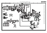
Scaler Board Schematic Diagram-PIN STATUS DEFINITION
S-18
Summary of Contents for 19PFL5402D/27
Page 2: ......
Page 43: ...41 TPM1 0U LA 7 Circuit Diagrams and PWB Layouts Scaler Board Layout Top Side Part 1 ...
Page 44: ...42 TPM1 0U LA 7 Circuit Diagrams and PWB Layouts Scaler Board Layout Top Side Part 2 ...
Page 45: ...43 TPM1 0U LA 7 Circuit Diagrams and PWB Layouts Scaler Board Layout Top Side Part 3 ...
Page 46: ...44 TPM1 0U LA 7 Circuit Diagrams and PWB Layouts Scaler Board Layout Top Side Part 4 ...
Page 89: ...10 31 TPM1 0U LA 87 9 Circuit Descriptions Abbreviations List and IC Data Sheets ...
Page 141: ...39 TPM1 0U LA 7 Circuit Diagrams and PWB Layouts Scaler Board Layout ...
Page 142: ...40 TPM1 0U LA 7 Circuit Diagrams and PWB Layouts Scaler Board Layout TOP LEFT ...
Page 143: ...41 TPM1 0U LA 7 Circuit Diagrams and PWB Layouts Scaler Board Layout TOP RIGHT ...
Page 144: ...42 TPM1 0U LA 7 Circuit Diagrams and PWB Layouts Scaler Board Layout BUTTOM LEFT ...
Page 145: ...43 TPM1 0U LA 7 Circuit Diagrams and PWB Layouts Scaler Board Layout BUTTOM RIGHT ...
Page 146: ...44 TPM1 0U LA 7 Circuit Diagrams and PWB Layouts Scaler Board Layout 2 ...
Page 147: ...45 TPM1 0U LA 7 Circuit Diagrams and PWB Layouts Scaler Board Layout 2 TOP LEFT ...
Page 148: ...46 TPM1 0U LA 7 Circuit Diagrams and PWB Layouts Scaler Board Layout 2 TOP RIGHT ...
Page 149: ...47 TPM1 0U LA 7 Circuit Diagrams and PWB Layouts Scaler Board Layout 2 BUTTOM LEFT ...
Page 150: ...48 TPM1 0U LA 7 Circuit Diagrams and PWB Layouts Scaler Board Layout 2 BUTTOM RIGHT ...
Page 191: ...89 TPM1 0U LA 9 Circuit Descriptions Abbreviations List and IC Data Sheets ...


