9
190X6&170X6 LCD
Go to cover page
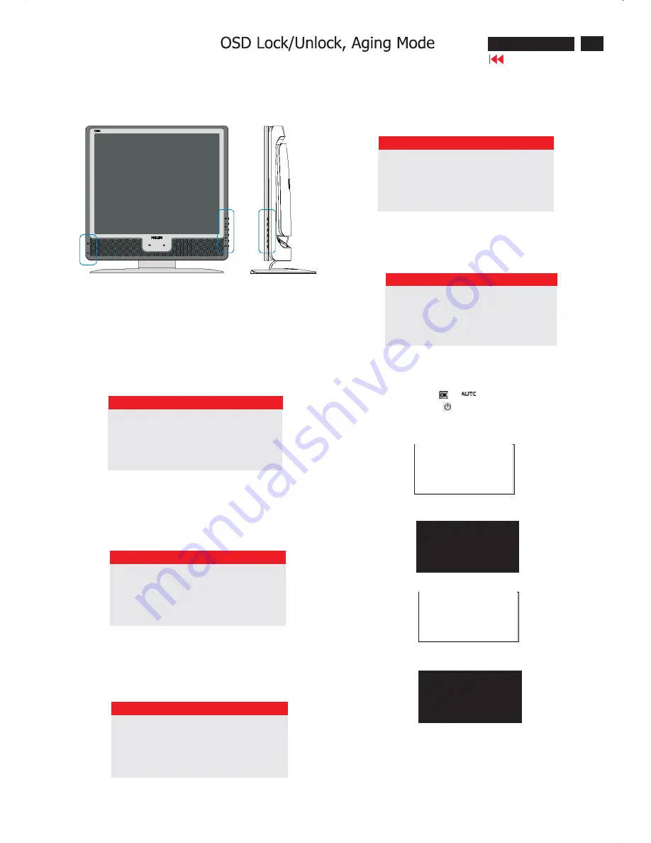
Front Control Panel
To Lock/Unlock OSD FUNCTION(User Mode)
The OSD function can be locked by pressing"OK"button(1) for more
than 10 seconds, the screen shows following windows for 3 seconds.
Everytime when you press"AUTO" or "OK" button, this message app-
ears on the screen automatically.
ATTENTION SIGNAL
OSD MAIN CONTROLS UNLOCKED
Unlock OSD function
Locked OSD function can be released by pressing "OK" button for more
than 10 seconds again
ATTENTION SIGNAL
OSD MAIN CONTROLS LOCKED
NO VIDEO INPUT
This screen appears if there is no video signal input. Please check that
the signal is properly connected to the video card of PC and make sure
PC is on
ATTENTION SIGNAL
CHECK CABLE CONNECTION
CANNOT DISPLAY THIS VIDEO MODE..
This screen warns when the input frequency from the computer is not
a standard video mode or out of the monitor's scanning range.
Please change the display mode of the operating software in the com-
puter(i.e.windows) to 1280*1024@60HZ for best display results.
ATTENTION SIGNAL
CANNOT DISPLAY THIS VIDEO
MODE,CHANGE COMPUTER DISPLAY
INPUT TO 1280*1024@60HZ
I
WAIT FOR AUTOMATIC ADJUSTMENT
This screen appears when you press the "AUTO" buttons at the same
time. It will disappear when the monitor is properly adjusted
ATTENTION SIGNAL
WAITING FOR AUTOMATIC ADJUSTMENT
Access Aging.. Mode
Step 1 : Turn off LCD monitor, and disconnect Interface Cable
between Monitor and PC.
Step 2 : [Push AUTO "
" & "
" buttons at the same time and
hold it]+[Press power "
" button until comes out " AGING screen"
] => then release all buttons.
Bring up:
AGING...
After 15 seconds, bring up:
After 15 seconds, bring up:
AGING...
After 15 seconds, bring up:
----------
----------
repeatly
Connect Signal cable again=> go back to normal display
Summary of Contents for 170X6FB/00
Page 8: ...8 190X6 170X6 LCD Go to cover page On Screen Display ...
Page 37: ...37 190X6 170X6 LCD Wiring Diagram 170X6 Go to cover page ...
Page 38: ...38 190X6 170X6 LCD Go to cover page Go to cover page Wiring Diagram 190X6 ...
Page 40: ...Scaler Diagram Go to cover page 40 190X6 170X6 LCD ...
Page 41: ...Scaler Diagram 41 190X6 170X6 LCD ...
Page 42: ...Scaler Diagram Go to cover page 42 190X6 170X6 LCD ...
Page 43: ...Scaler Diagram 43 190X6 170X6 LCD ...
Page 44: ...Scaler Diagram Go to cover page 44 190X6 170X6 LCD ...
Page 45: ...Scaler Board C B A 45 190X6 170X6 LCD ...
Page 46: ...Scaler Board C B A Go to cover page 46 190X6 170X6 LCD ...
Page 47: ...AUDIO DIAGRAM 170X6 47 190X6 170X6 LCD ...
Page 48: ...AUDIO DIAGRAM 170X6 Go to cover page 48 190X6 170X6 LCD ...
Page 49: ...Audio Board C B A 170X6 49 190X6 170X6 LCD ...
Page 50: ...Audio Board C B A 170X6 Go to cover page 50 190X6 170X6 LCD ...
Page 51: ...AUDIO DIAGRAM 190X6 51 190X6 170X6 LCD ...
Page 52: ...AUDIO DIAGRAM 190X6 Go to cover page 52 190X6 170X6 LCD ...
Page 53: ...Audio Board C B A 190X6 53 190X6 170X6 LCD ...
Page 54: ...Audio Board C B A 190X6 Go to cover page 54 190X6 170X6 LCD ...
Page 55: ...POWER DIAGRAM 55 190X6 170X6 LCD ...
Page 56: ...POWER DIAGRAM Go to cover page 56 190X6 170X6 LCD ...
Page 57: ...Power Board C B A 57 190X6 170X6 LCD ...
Page 58: ...USB DIAGRAM Go to cover page 58 190X6 170X6 LCD ...
Page 59: ...USB Board C B A 59 190X6 170X6 LCD ...
Page 60: ...USB Board C B A Go to cover page 60 190X6 170X6 LCD ...
Page 61: ...CONTROL EARPHONE DIAGRAM 61 190X6 170X6 LCD ...
Page 62: ...Control Board C B A Go to cover page 62 190X6 170X6 LCD ...


