


12
Display Adjustment
Alignment procedure
1. Turn on the LCD monitor.
2.Turn on the Timing/pattern generator. See Fig.1
Resolution :1280x1024(Use the best resolution)
Timing : H= 31.47KHz V=60Hz
3. Preset LCD color Analyzer CA-110
-Remove the lens protective cover of probe CA-A30.
-Set measuring/viewing selector to measuring position for reset
analyzer.(zero calibration) as Fig.2
- Turn on the color analyzer (CA-110)
-Press 0-CAL button to starting reset analyzer. See Fig.3
Fig. 1
Fig. 2
Cover (black)
Cover (black)
Measurement viewing selector
Measurement viewing selector
N
ote: after alignment
,
please reset
O
SD to user s mode for normal
operation.
O
therwise
,
the monitor won t entering power saving mode
and showing full white picture all the time as no video signal supplied.
To leave factory mode by restart the monitor.
5
.
Ad
j
ust
O
SD menu to lower position of screen (i.g. ad
j
ust V-position to
value
"
0
"
at submenu of
O
SD Setting.
6.
Setting
B
rightness and Contrast
- Ad
j
ust
B
rightness to value
" 9
0
"
.
- Ad
j
ust Contrast to value
"
80
"
.
7.
Switch light probe to Viewing position.
8.
Move the Lens barrel forward or backward to get clear image as
shown in Fig. 4
9
.
Switch light probe to Measuring position.
I
t should be able to indicate
Clear image
Clear image
Measurement/viewing selector
Measurement/viewing selector
Alignment hits: 1. R for x value
, G
for y value
, B
for
Y
value on the
colour analyzer.
2.
I
f the colour analyzer has been calibrated and preset
colour temperature in it. Please switch to correct
setting in accordance with colour settings.
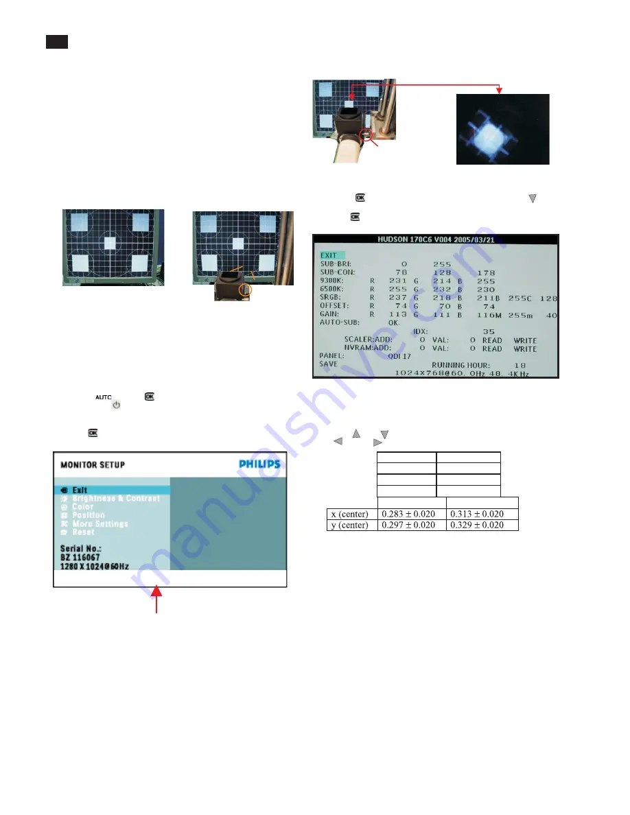
4. Access Factory Mode
How to get into Factory Mode Menu
Step1:
Turn off monitor.
Step2:
[Push AUT
O "
"
&
O
K
"
"
buttons at the same time and hold it]
+[Press power
"
"
button untill comes out
"
Windows screen
"
]
=> then release all buttons
Step3:
Press
O
K
"
"
button
,
bring up Factory mode indication as shown
in Fig3.
Fig. 3
10. Setting pattern to full white picture
11. Press
button
,
then select factory mode indicator by
"
"
"
"
button
12. Press
"
"
button to bring up submenu windows as below:
13. Press
"
"
or
"
"
button to select R
G B
. Change the value by
"
"
or
"
"
key until the X
,Y
co-ordinates as below
sRGB
x(center)
0.313
±
0.008
y(center)
0.329
±
0.008
Ynits
180
±
10
9300
°
K
6500
°
K
Fig.4
1
5
.
EE
PR
O
M presetting (
B
)
After finishing all the ad
j
ustment
,
set:
B
rightness control to 100
%
Contrast control to
5
0
%
O
SD position at middle of screen
C
O
L
O
R ad
j
usts to 6
5
00K color.
HUDSON 170C6 V004 2005/03/21
Factory mode indicaor
Summary of Contents for 170C6FS/00
Page 16: ...16 Wiring Diagram 17 ...
Page 18: ...Scaler Schematic Diagram 1 18 ...
Page 19: ...Scaler Schematic Diagram 2 19 ...
Page 20: ...Scaler Schematic Diagram 3 20 ...
Page 21: ...Scaler Schematic Diagram 4 21 ...
Page 22: ...Scaler Board C B A 1 22 ...
Page 23: ...Scaler Board C B A 2 23 ...
Page 24: ...Control Schematic Diagram C B A 24 ...
Page 25: ...25 Power Board Block Diagram Delta ...
Page 26: ...26 Power Board Schematic Diagram Delta ...
Page 27: ...27 Power Board Schematic Diagram Delta ...
Page 28: ...28 Power Board C B A Delta ...
Page 29: ...29 Power Board Schematic Diagram Lien Chang ...
Page 30: ...30 Power Schematic Diagram Lien Chang ...
Page 31: ...Power Board C B A Lien Cheng 31 AIP 0093 ...
Page 40: ...40 Repair Flow Chart ...
Page 41: ...41 Repair Flow Chart ...
Page 42: ...42 Repair Flow Chart ...


