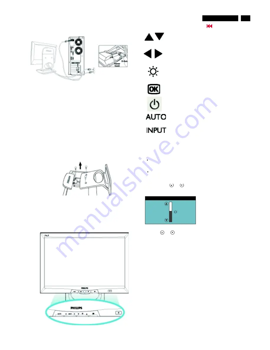
Installation
Go to cover page
Front View Product Description
UP and DOWN buttons are used when adjusting
the OSD of your monitor
LEFT and RIGHT buttons, like the UP and DOWN
buttons, are also used in adjusting the OSD of your
monitor.
BRIGHTNESS hotkey. When the UP and DOWN
arrow buttons are pressed, the adjustment controls
for the BRIGHTNESS will show up.
OK button which when pressed will take you to the
OSD controls
POWER button switches your monitor on
Automatically adjust the horizontal position, vertical
position, phase and clock setting.
Signal inputs selective hotkeys. Allows user to
switch between two video connectors (D-Sub &
DVI-D), e.g. D-Sub <-> DVI-D digital inputs.
Connecting to Your PC
1) Thread power cord through the hole at the bottom of the base,
and plug onto monitor firmly.
2) Double check all cables' connection closely. Make sure they are
all connected well.
Note: If you use an Apple Macintosh , you need to connect the
special Mac adapter to one end of the monitor signal cable.
3) Connect to PC
(A) Turn off your computer and unplug its power cable.
(B) Connect the monitor signal cable to the video connector
on the back of your computer.
(C) Plug the power cord of your computer and your monitor
into a nearby outlet.
(D) Turn on your computer and monitor. If the monitor
Displays an image, installation is complete.
TM
Remove the Base
1) (a) Tilt monitor on certain angle.
(b) Pull cables out of the hole at the bottom of base.
2) (a) Put monitor face down on the safe surface.
(b) Take off the cap of base
3) Unscrew the four screws of the base
Performing auto-adjustment of the monitor
Adjusting the brightness
Press the AUTO button.
The picture quality (
,
) and picture position will be
optimally adjusted for your system.
Press the MENU button to save the settings.
The brightness of the monitor is adjusted directly with the arrow
buttons.
PHASE CLOCK
Press the button
or
.
BRIGHTNESS
Press the
or
button to adjust the brightness.
The setting window disappears after approximately 60 seconds if no
further setting is made.
All changes are stored automatically.
B R I G H T N E S S
50
The window
with a setting scale is visualised.
5
170B4&S4
Summary of Contents for 170B4BB
Page 32: ...32 170B4 S4 9 Go to cover page D sub DVI Schematic Diagram ...
Page 33: ...ROM Schematic Diagram 33 9 Go to cover page 170B4 S4 ...
Page 34: ...34 170B4 S4 9 Go to cover page Scaler Board Schematic Diagram ...
Page 35: ...35 9 Go to cover page 170B4 S4 Power Schematic Diagram ...
Page 36: ...36 9 Go to cover page 170B4 S4 C B A Scaler Board ...
Page 37: ...36 1 9 Go to cover page 170B4 S4 C B A Scaler Board ...
Page 38: ...37 9 Go to cover page 170B4 S4 C B A Scaler Board ...
Page 39: ...37 1 9 Go to cover page 170B4 S4 C B A Scaler Board ...
Page 40: ...38 170B4 S4 9 Go to cover page Power Shematic Diagram ...
Page 41: ...9 Go to cover page 170B4 S4 C B A Power Board 44 39 ...
Page 42: ...39 1 9 Go to cover page 170B4 S4 C B A Power Board ...
Page 43: ...40 9 Go to cover page 170B4 S4 Schematic diagram Control ...


