CLOCK & PHASE Adjustments
27
Go to cover page
170B4&S4
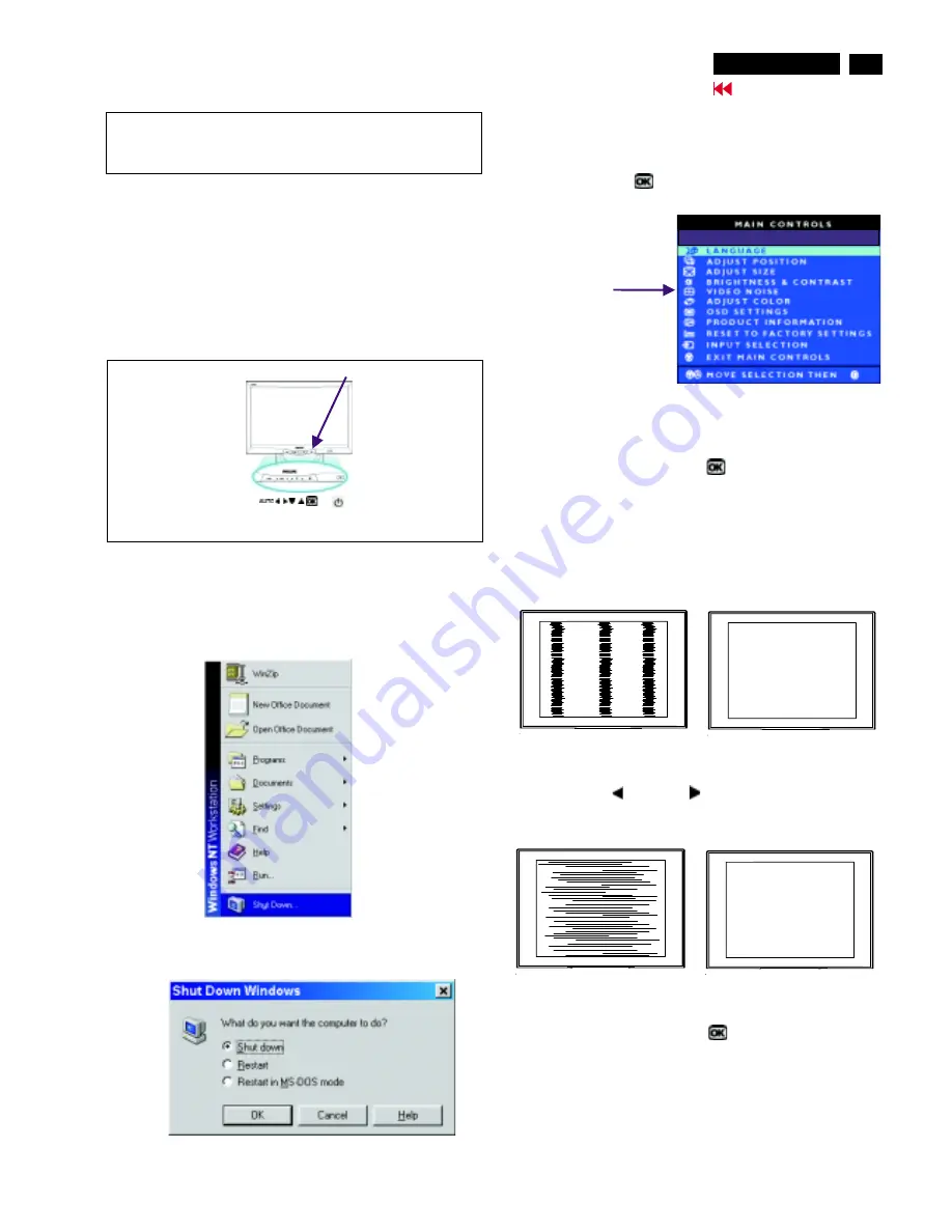
Step 1 : Click on the Start button (Win95, Win98 or Win NT)
and choose " Shut Down...". as shown in Fig. 2.
Step 2 : The menu of " Shut Down Windows " is as shown in Fig. 3
Step 3 : Retain Shut Down Window on the screen , follow
the CLOCK and PHASE adjustment instructions for the
optimal video display.
PHASE phenomenon
Due to the different quality of video signal generated from graphics
cards. By press AUTO button for
t is necessary to adjust
CLOCK and PHASE functions for the optimal video display of LCD
monitor by manual. Following steps will guide you to make correct
adjustment of CLOCK and PHASE.
However, CLOCK and PHASE functions are only available while analog
video signal is supplied. Operating unit under digital signal state, the
video clock information can be obtained from graphics cards directly.
Therefor, it is unnecessary to adjust these functions.
CLOCK and PHASE adjustment
automatically. Sometimes, the deviation of video signal which generated
from graphics cards is out of control, then i
Manual adjustment
If the quility of display still poor or flicker, you may also improve it by
manual adjust CLOCK and PHASE functions to eliminate the flicker.
Step 4 : Press the OK
button to bring up MAIN CONTROLS
(OSD menu).
Step 8 : Press Left
or Right
to adjust PHASE.
The picture will be adjusted as following figure, adjust PHASE
and check the picture, stop at the point that without any vertical
jitter bar remaining on the screen.
button
Step 5 : Select Video Noise by press
button,
bring up it’s submenu.
Step 6 : Using UP or DOWN button to select "CLOCK" or "PHASE".
Step 7 : Press Left
or Right
to adjust CLOCK. The
picture will be adjusted as following figure, adjust CLOCK to
fine-tune the video until optimal display is obtained.
button
Step 9 : Quit OSD menu by press OK
button to save the settings.
CLOCK Phenomenon
Video Noise
The monitor has build-in a auto adjustment hotkey on the front panel,
you may obtained a optimal video display by simply press the
button and save the settings. CLOCK, PHASE, Vertical position, and
Horizontal position are adjusted automatically.
AUTO
Fig. 4
Fig. 2
(Before)
(Before)
(After)
(After)
Fig. 3 (Win 98)
Front control panel
1 = Buttons for the OSD menu (On-Screen-Display)
2 = Power button
(OK button for OSD lock/unlock)
Fig. 1
-------------->
---------->
AUTO
(OK)
1
2
USE 1280 x 768 FOR BEST RESULT
USE 1280 x 768 FOR BEST RESULT
Summary of Contents for 170B4BB
Page 32: ...32 170B4 S4 9 Go to cover page D sub DVI Schematic Diagram ...
Page 33: ...ROM Schematic Diagram 33 9 Go to cover page 170B4 S4 ...
Page 34: ...34 170B4 S4 9 Go to cover page Scaler Board Schematic Diagram ...
Page 35: ...35 9 Go to cover page 170B4 S4 Power Schematic Diagram ...
Page 36: ...36 9 Go to cover page 170B4 S4 C B A Scaler Board ...
Page 37: ...36 1 9 Go to cover page 170B4 S4 C B A Scaler Board ...
Page 38: ...37 9 Go to cover page 170B4 S4 C B A Scaler Board ...
Page 39: ...37 1 9 Go to cover page 170B4 S4 C B A Scaler Board ...
Page 40: ...38 170B4 S4 9 Go to cover page Power Shematic Diagram ...
Page 41: ...9 Go to cover page 170B4 S4 C B A Power Board 44 39 ...
Page 42: ...39 1 9 Go to cover page 170B4 S4 C B A Power Board ...
Page 43: ...40 9 Go to cover page 170B4 S4 Schematic diagram Control ...


