18
150B LCD
Go to cover page
Forward
Back
DDC Instructions(Continued)
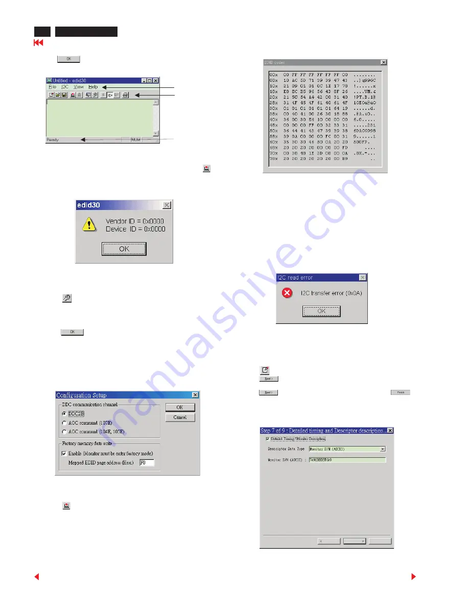
Loading DDC data from monitor
1. Click
icon on the tools bar to bring up the Configuration Setup
windows as Fig.7
2. Select the DDC2B as the communication channel.
3. Enable Factory memory data write function and fill in page address
“F0” to the block.
4.. Click
button to confirm your selection.
Note: The Factory memory data write function will allow EDID30 to
rewrite serial numbers both Analog DDC IC and main EEPROM to
make sure both S/N are exactly the same. You may confirm the
function by checking the S/N at Product information of the OSD
menu after restarting the monitor.
5. Click
button. The main menu appears (as shown on Fig. 6).
Fig. 6
Note: If the connection is improper, you will see the following error
message before entering the main menu. Meanwhile, the
(read EDID) function will be disable. At this time, please make
sure all cables are connected correctly and fixedly, and the
procedure has been performed properly.
4. Click
icon to read DDC EDID data from monitor. The EDID
codes will display on screen as following. (The EDID codes are
depend on the model.) Meanwhile, The status bar will indicate 00%
to 100% when reading.
Back
Next
Cancel
Command bar
Tools bar
Status bar
Fig. 7
Modify DDC data (Serial No.)
1. Click
icon on the toosl bar.
2. Click
till the Step 7 of 9 window appears.
3. Type the new Serial No. (for example, 7492DBD8TGA9).
4. Click
till the last step window appears, then click
to
exit the Step window.
Note: During the loading, EDID30 will verify the EDID data which just
loaded from monitor before proceed any further function, once
the data structure of EDID can not be recognized, the following
error message will appear on the screen (Fig. 8). Please confirm
following steps to avoid this message.
1. The data structure of EDID was incorrect.
2. DDC IC that you are trying to load data is empty.
3. Wrong communication channel has set at configuration setup
windows.
4. Cables loosed or poor contact of connection.
Fig. 8


