background image

13

SAFETY PRECAUTIONS

Please read all instructions before attempting to unpack, install or 

operate this equipment and before connecting the power supply.
Please keep the following in mind as you unpack and install this 

equipment:

Always follow basic safety precautions to reduce the risk of fire,

electrical shock and injury to persons.

To prevent fire or shock hazard, do not expose the unit to rain,

moisture or install this product near water.

Never spill liquid of any kind on or into this product.

Never push an object of any kind into this product through any

openings or empty slots in the unit, as you may damage parts

inside the unit.

Do not attach the power supply cabling to building surfaces.

Use only the supplied power supply unit (PSU). Do not use the PSU

if it is damaged.

Do not allow anything to rest on the power cabling or allow any

weight to be placed upon it or any person walk on it.

To protect the unit from overheating, do not block any vents or

openings in the unit housing that provide ventilation and allow for

sufficient space for air to circulate around the unit.

REVISION HISTORY

VERSION NO. DATE (DD/MM/YY) SUMMARY OF CHANGE

RDV1

.3

01

/

10

/15

Preliminary release

13

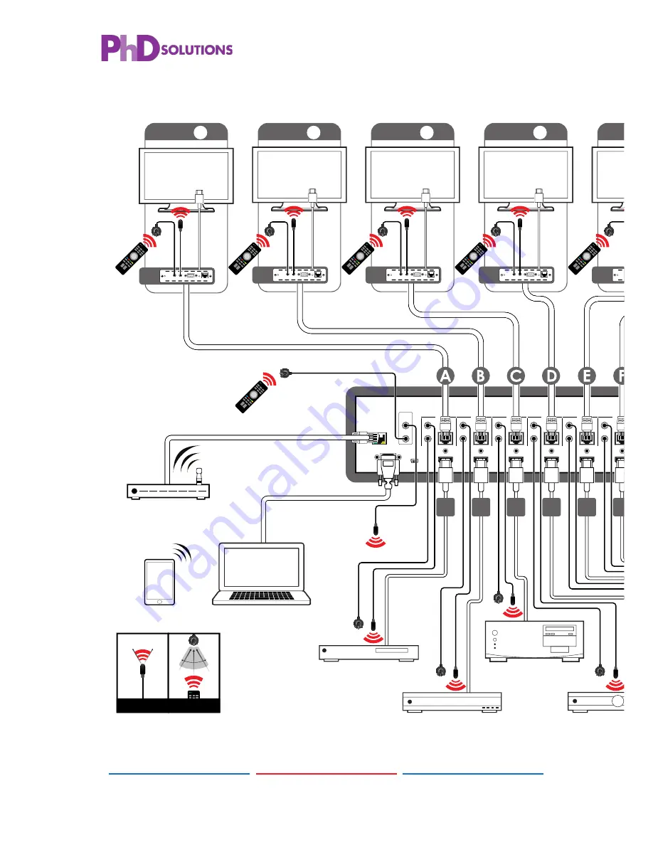
7. CONNECTION DIAGRAM

CONTROL

RS232

SERVICE

IR OUT

IR IN

IR OUT

IR IN

IR OUT

IR IN

ALL

A

B

C

D

E

F

G

H

CAT5e/6 OUT

IR OUT

IR IN

CAT5e/6 OUT

IR OUT

IR IN

CAT5e/6 OUT

IR OUT

IR IN

CAT5e/6 OUT

IR OUT

IR IN

CAT5e/6 OUT

IR OUT

IR IN

CAT5e/6 OUT

CAT5e/6 OUT

IR OUT

IR IN

CAT5e/6 OUT

MAIN 24V

POE 24V

1

HDMI IN

2

HDMI IN

3

HDMI IN

4

HDMI IN

5

HDMI IN

6

HDMI IN

7

HDMI IN

8

HDMI IN

1

2

3

4

V+

GND

GND

GND

V+

ZONE


A

1

2

3

4

5

6

8

7

RX

ZONE


B

Power

Extender Blaster

IR 2

IR 1

RS232 Out

CAT5e/6 In

Link

RX

Power

Extender Blaster

IR 2

IR 1

RS232 Out

CAT5e/6 In

Link

ZONE


C

RX

Power

Extender Blaster

IR 2

IR 1

RS232 Out

CAT5e/6 In

Link

ZONE


D

RX

Power

Extender Blaster

IR 2

IR 1

RS232 Out

CAT5e/6 In

Link

RX

Power

Extender Blaster

IR 2

IR 1

RS232 Out

CAT5e/6 In

Link

RX

Power

Extender Blaster

IR 2

IR 1

RS232 Out

CAT5e/6 In

Link

RX

Power

Extender Blaster

IR 2

IR 1

RS232 Out

CAT5e/6 In

Link

ZONE

E

ZONE

F

ZONE

G

ZONE

H

RX

Power

Extender Blaster

IR 2

IR 1

RS232 Out

CAT5e/6 In

Link

IR BLASTER

1.5m

60°

IR EXTENDER

7m

3m

3m

60°

m

Main Power Supply

Power Supply for

Power-over-Cable

IR Out 

(All)

LAN

RS-232

IR In 

(ALL)

Receiver Units

CAT5e/6/7 

Cable

HDMI Inputs

IR In/Out

HDMI Outputs

IR In/Out

Source 

Equipment

Displays

RS-232 Equipped

PC or Notebook

Wireless Router 

(with Internet 

Connection) 

Smartphone or 

Tablet Device

Summary of Contents for MXC-UHD-P8X8-HDTL

Page 1: ...MXC UHD P8X8 HDTL 8 8 HDMI 4K UHD over CAT5e 6 7 Matrix with HDCP 2 2 Operation Manual Operation Manual...

Page 2: ......

Page 3: ...RS The information in this manual has been carefully checked and is believed to be accurate PhD Solutions assumes no responsibility for any infringements of patents or other rights of third parties wh...

Page 4: ...ugh any openings or empty slots in the unit as you may damage parts inside the unit Do not attach the power supply cabling to building surfaces Use only the supplied power supply unit PSU Do not use t...

Page 5: ...ctions 3 6 1 Front Panel 3 6 2 Rear Panel 4 6 3 Side Panel 5 6 4 Remote Control 6 6 5 IR Cable Pin Assignment 6 6 6 RS 232 Protocol 7 6 7 RS 232 and Telnet Commands 7 6 8 Telnet Control 9 6 9 WebGUI C...

Page 6: ...tall this product near water Never spill liquid of any kind on or into this product Never push an object of any kind into this product through any openings or empty slots in the unit as you may damage...

Page 7: ...r HDMI equipped AV receivers connect with HDMI cables Industry standard CAT5e 6 7 cables HDBaseT Receivers 5 FEATURES HDMI with 4K2K supported HDCP 2 2 and DVI compliant Supports PC resolution up to W...

Page 8: ...d of any kind on or into this product Never push an object of any kind into this product through any openings or empty slots in the unit as you may damage parts inside the unit Do not attach the power...

Page 9: ...Connect to an active network for Telnet and Web GUI control refer to Sections 6 8 and 6 9 Warning Please do not connect this port directly to the PC Laptop as the Telnet function will not work 2 RS 23...

Page 10: ...asic safety precautions to reduce the risk of fire electrical shock and injury to persons To prevent fire or shock hazard do not expose the unit to rain moisture or install this product near water Nev...

Page 11: ...ions 1 3 Package Contents 1 4 System Requirements 2 5 Features 2 6 Operation Controls and Functions 3 6 1 Front Panel 3 6 2 Rear Panel 4 6 3 Side Panel 5 6 4 Remote Control 6 6 5 IR Cable Pin Assignme...

Page 12: ...ow basic safety precautions to reduce the risk of fire electrical shock and injury to persons To prevent fire or shock hazard do not expose the unit to rain moisture or install this product near water...

Page 13: ...esolutions 16 9 Acronyms 17 8 COMMAND DESCRIPTION PARAMETER SETIP x x x x x x x x x x x x Set IP SubNet and Gateway Static IP X 0 255 IPCONFIG Display the current IP configuration NONE RSTIP Set IP co...

Page 14: ...supply Please keep the following in mind as you unpack and install this equipment Always follow basic safety precautions to reduce the risk of fire electrical shock and injury to persons To prevent fi...

Page 15: ...age Contents 1 4 System Requirements 2 5 Features 2 6 Operation Controls and Functions 3 6 1 Front Panel 3 6 2 Rear Panel 4 6 3 Side Panel 5 6 4 Remote Control 6 6 5 IR Cable Pin Assignment 6 6 6 RS 2...

Page 16: ...and before connecting the power supply Please keep the following in mind as you unpack and install this equipment Always follow basic safety precautions to reduce the risk of fire electrical shock and...

Page 17: ...2 Applications 1 3 Package Contents 1 4 System Requirements 2 5 Features 2 6 Operation Controls and Functions 3 6 1 Front Panel 3 6 2 Rear Panel 4 6 3 Side Panel 5 6 4 Remote Control 6 6 5 IR Cable Pi...

Page 18: ...ury to persons To prevent fire or shock hazard do not expose the unit to rain moisture or install this product near water Never spill liquid of any kind on or into this product Never push an object of...

Page 19: ...emote Control 6 6 5 IR Cable Pin Assignment 6 6 6 RS 232 Protocol 7 6 7 RS 232 and Telnet Commands 7 6 8 Telnet Control 9 6 9 WebGUI Control 11 7 Connection Diagram 13 8 Specification 15 8 1 Technical...

Page 20: ...the risk of fire electrical shock and injury to persons To prevent fire or shock hazard do not expose the unit to rain moisture or install this product near water Never spill liquid of any kind on or...

Page 21: ...2 5 Features 2 6 Operation Controls and Functions 3 6 1 Front Panel 3 6 2 Rear Panel 4 6 3 Side Panel 5 6 4 Remote Control 6 6 5 IR Cable Pin Assignment 6 6 6 RS 232 Protocol 7 6 7 RS 232 and Telnet...

Page 22: ...e keep the following in mind as you unpack and install this equipment Always follow basic safety precautions to reduce the risk of fire electrical shock and injury to persons To prevent fire or shock...

Page 23: ...lutions products are covered by a one year PARTS and LABOUR warranty depending on the product Please contact your PhD Solutions dealer for details During this period there will be no charge for unit r...

Page 24: ...e unit beyond that described in these operating instructions Refer all other servicing to authorised PhD Solutions servicing personnel Return to Supplier When shipping the unit carefully pack and send...

Page 25: ...ns remove or re install previously installed equipment travel to and from service location loss of or damage to media images data or other recorded stored content ANY PARTS AND SERVICE NOT COVERED BY...

Page 26: ......

Page 27: ......

Page 28: ...PREMIUM high DEFINITION Solutions Home page http www phdsolutions co 21...

Reviews: