


3)7*67$1'$5'
86$
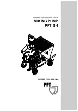
2YHUYLHZ
BBBBBBBBBBBBBBBBBBBBBBBBBBBBBBBBBBBBBBBBBBBBBBBBBBBBBBBBBBBBBBBBBBBBBBBBBBBBBBBBBBBBBBBB
________________________________________________________________________________________
1. Pump Motor
7. Water manifold
2. Mixing tube
8. Water inlet
3. Material hopper
9. Control box
4. Compressor
10. Tool box
5. Mortar output flange
11. Mixing Tube with Suction Flange
6. Pumping System TWISTER
Summary of Contents for PFT G4
Page 1: ...OPERATING INSTRUCTIONS 0 1 3803 3 7 3 7 1 6 029 1...
Page 2: ......
Page 66: ......
Page 67: ......