background image

Installing Your UPS

HARDWARE INSTALLATION GUIDE

1.

Your new UPS may be used immediately upon receipt.

However,

recharging the battery for at least four hours is rec-

ommended

to insure that the battery’s maximum charge capacity

is achieved. Charge loss may occur during shipping and storage. 

To recharge the battery, simply leave the unit plugged into an AC

outlet. The unit will charge in both the ON as well as the OFF

position. If you wish to use the software, connect the enclosed

serial interface cable to the serial port on the UPS and an open

serial port on the computer.  

2.

With the UPS unit OFF and unplugged, plug your equipment

into the unit’s rear panel AC outlets.  

DO NOT

plug a laser printer,

copier, space heater, vacuum cleaner, paper shredder or other

large electrical device into the UPS.  The power demands of

these devices will overload and possibly damage 

the unit.

3.

To protect a telephone modem line (DVR or Satellite TV

receiver) or network cable, connect a telephone cable or network

cable from the wall jack outlet to the IN jack of the UPS.  Then

connect a telephone cable or network cable from the OUT jack 

on the UPS to the equipment’s telephone jack or network device.

Note:

This unit provides both telephone and

LAN protection on one set of RJ-11/45 jacks.

The telephone circuit uses pins 4 & 5 while the

LAN circuit uses pins 1, 2, 3 & 6.  Adapters or

custom cables (not included) must be used

when utilizing both protection circuits at the same time. 

4.

Plug the UPS into a 2 pole, 3 wire grounded receptacle (wall

outlet). Make sure the wall branch outlet is protected by a fuse or

circuit breaker and does not service equipment with large electri-

cal demands (e. g. refrigerator, copier, etc.)  Avoid using exten-

sion cords.  If used, the extension cord must be UL or CSA

Listed, minimum 14 AWG, 3-wire grounded, and rated for 15

Amps.

5. 

Press the power switch to turn the UPS on.  The Power ON

indicator light will illuminate.  

6.

The rear panel circuit breakers will open and power to the con-

nected equipment will be turned OFF if an overload is detected.

To correct this, turn the UPS off, unplug at least one piece of

equipment, wait 10 seconds, check to make sure that the circuit

breakers are reset, and turn the unit on.

7. 

The UPS will automatically charge the battery whenever it is

plugged into an AC outlet,

8.

To maintain optimal battery charge, leave the UPS plugged

into an AC outlet at all times.

Note: 

To store your UPS for an extended period, cover it and

store with the battery fully charged. Recharge the battery every

three months to ensure battery life.

2

USA & Canada (800) 472-5555  

• 

 (707) 283-5900  

• 

 Fax (707) 283-5901

FRONT PANEL DESCRIPTION

M1500-UPS-PFP

Pure Sine Wave

Intelligent Critical Load Control

UNSAFE VOLTAGE

LINE FAULT

POWER ON

AVR MODE

BATTERY MODE

BATTERY LEVEL

LOAD LEVEL

POWER

TEST

Power Switch

Press the power

button to turn the

UPS ON or OFF.

Removable Access Panel

Easy to remove for battery access and

replacement. 

Note: DO NOT lift product with han-

dles. They are for panel removal

only.

Test Switch

This UPS performs a self-test automatically when powered on.  The test switch allows

you to test the system at any time.  When the UPS passes the test, it returns to on-

line operation.  If the UPS fails the self-test, please recharge the battery for 4 hours

and perform another self-test.  If it fails after recharging the battery, please replace

the battery.  In battery mode, you can press this button to silence an audible alarm.

Basic Operation

RJ-45

1  2  3  4  5  6  7  8

LAN

TEL

Summary of Contents for M1500-UPS-PFP

Page 1: ...NSAFE VOLTAGE LINE FAULT POWER ON AVR MODE BATTERY MODE BATTERY LEVEL LOAD LEVEL The M1500 UPS PFP is a Programmable Uninterruptible Power Supply Voltage Regulator Power Conditioner INS00836 REV C 11 08 UNITED STATES PATENT I S P R O T ECTED BY PATENT NUM B E R S T E C H N O L OGY UTILIZED ON THIS P R O D U C T 7 245 470 ...

Page 2: ...tions pg 12 RS232 Communications Protocol Command Set pgs 13 14 15 16 FCC Notice and Warranties pg 17 Table of Contents Before You Begin 2 Power Cord 1 UPS Unit 3 Phone Cord 5 Rack Mounting Kit 4 DB 9 Serial Cable 6 Power Control Software CD Inspect the UPS upon receipt In addition to this manual the box should contain the following UNPACKING POWER TEST MAX Home Cinema UPS Pure Sine Wave Intellige...

Page 3: ...ve contaminants Please see specifications for acceptable temperature and humidity range CAUTION To reduce the risk of electric shock do not remove the cover except to service the battery No user serviceable parts inside except for the battery CAUTION To avoid electrical shock turn off the unit and unplug it from the AC power source before servicing the battery or installing a component CAUTION DO ...

Page 4: ...large electri cal demands e g refrigerator copier etc Avoid using exten sion cords If used the extension cord must be UL or CSA Listed minimum 14 AWG 3 wire grounded and rated for 15 Amps 5 Press the power switch to turn the UPS on The Power ON indicator light will illuminate 6 The rear panel circuit breakers will open and power to the con nected equipment will be turned OFF if an overload is dete...

Page 5: ...uminate when the load is above 25 the 2nd above 50 and the 3rd above 75 The 4th arrow will flash when the load is between 85 and 100 Battery Level Indicator This is a visual indication of the battery charge If battery capac ity is under 25 no indicator LED will illuminate and UPS starts beeping if the audible alarm is enabled 3 USA Canada 800 472 5555 707 283 5900 Fax 707 283 5901 FRONT PANEL DISP...

Page 6: ...nt to both outputs The IR LED s will flash once per second during the delay time and will stop flashing after the IR code is sent 2 If the delay settings are the same for both IR1 and IR2 the IR2 code will be sent to both outputs 2 seconds after IR1 3 The IR commands will also be transmitted immediately after the battery charge falls below the critical load battery threshold This ensures that equi...

Page 7: ...continued Power Control Software The M1500 UPS PFP has one rear panel serial port that provides the ability to program special functions i e safely shutdown a PC application or integrate the UPS with a home automation system Use of the software is optional The communications protocol is open a programmer can write their own control program or integrate the UPS s programming control functions into ...

Page 8: ...ndows Run command 12 Follow the on screen instructions 13 Once the software has finished installing remove the disk and restart your computer For Windows NT 4 0 1 Click on Start point to Settings then click Control Panel 2 Double click on the UPS Icon 3 Remove the check mark from the box labeled UPS is installed on 4 Click OK 5 Acknowledge the message that the UPS is in an unknown state 6 Exit to ...

Page 9: ... and shutting down the PC during extended power failures This requires a permanent RS232 connection to the PC and having the M1500 UPS PFP software running in the back ground on the PC When a power failure occurs open files are saved under auto assigned file names or existing file names and the files closed The computer and UPS are automatically shut down to con serve battery power Files with auto...

Page 10: ...tware 12 Time between power failure and shutdown For use with a PC This is the user control lable delay between when the power fails and the software starts the shutdown process If unchecked and plugged into one of the critical load outlets the PC will run on battery until the low battery signal is received 2 minutes of backup time remaining and then start the shutdown process 11 Time between powe...

Page 11: ... of any scheduled startups and shutdowns 7 Delete Clears the selected item from the schedule 3 Turn Off Select the day date and time that you want the computer system to shutdown This is optional and has no effect on whether your computer will shut down during a power failure 5 Cancel Closes the window without saving any schedules even if one was added to the Schedule Display Window Does not can c...

Page 12: ...UPS PFP 3 year warranty PF Power will replace M1500 UPS PFP batteries if they fail within the 3 year product warranty period For battery replacement information and instructions please contact Panamax Customer Service at www pana max com or call 800 472 5555 If batteries fail after the M1500 UPS PFP 3 year product warranty then the customer is responsible for battery replacement For detailed batte...

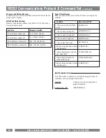
Page 13: ... boost 13 of input voltage for output regulation while input voltage is from 8 to 15 under nominal AVR Max boost 26 of input voltage for output regulation while input voltage is from 15 to 26 under nominal AVR Max buck 15 of input voltage for output regulation while input voltage is from 8 to 26 over nominal Utility Failure The UPS is providing battery power to the connected equipment Utility Fail...

Page 14: ... Lead acid___________________________________________________________________Yes User replaceable_____________________________________________________________Yes Typical recharge time _______________________________________________________8 hrs COMMUNICATION Software ___________________________________ Included Windows95 98 ME NT 2000 XP Hardware_______________________________________________ RS23...

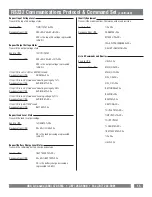
Page 15: ... outlets on and off to force a hard reboot of equipment Devices such as satellite receivers often crash and must be reset The following are commands made by the controller to the UPS AC INPUT BATTERY MAIN NCL To Non Critical Load NCL Outlets To Critical Load CL Outlets Stop bit _______________1 bit Parity ________________None Flow control ____________one Baud rate _______2400 bps Start bit _______...

Page 16: ...space 20 Hex XX is a number between 25 and 60 represented in ASCII If XX is a valid number between 25 and 60 Action Assigns the battery threshold variable with the value XX Response from UPS BTHRESH SP XX CR If XX is not valid Action None Response from UPS INVALIDCMD CR Enable Audible Alarm It is important that the UPS be as quiet as possible as it will be located in a home theater environment It ...

Page 17: ... is in AVR mode and bucking voltage by 11 Response from UPS AVRBUCK1 CR If the UPS is in BATTERY mode Response from UPS BATTERY CR Request Load Level Status Transmit the load level percentage Send to UPS LOADSTAT CR Response from UPS XX SP LOAD CR XX is the load percentage represented in ASCII Request Battery Charge Level Status Transmit the remaining battery charge percentage Send to UPS BATTERYS...

Page 18: ...in AVR or BATTERY mode UPS is in AVR boosting 13 UPS is in AVR boosting 26 UPS is in AVR bucking 15 UPS is in BATTERY mode Battery charge falls below critical load threshold Input voltage exceeds high volt age failure t hold Input voltage falls below low voltage failure t hold Battery charge falls below critical load threshold Response from UPS NORMAL CR AVRBOOST1 CR AVRBOOST2 CR AVRBUCK1 CR BATTE...

Page 19: ...l render the PFPower connected equipment protection policy null and void For additional information on how to protect your system please contact PFPower before connecting your equipment to the surge protector More detailed information is available at www pana max com or www furmansound com If you have any questions regarding these require ments please contact Customer Relations MODEL M1500 UPS PFP...

Page 20: ...1690 Corporate Circle Petaluma CA 94954 Tel 707 283 5900 Fax 707 283 5901 www panamax com www furmansound com ...

Reviews: