8
USA & Canada (800) 472-5555
•
(707) 283-5900
•
Fax (707) 283-5901
Power Control Software Instructions
(continued)
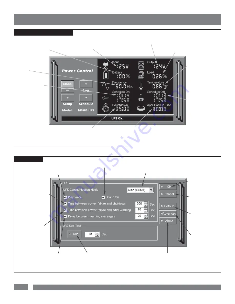
MAIN WINDOW DESCRIPTIONS
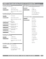
SETUP MENU
2. Input Voltage:
Shows the current input
voltage. The input normally appears in green, but
will turn red if the input voltage is lower than 85v
or higher than 150v.
9. Scheduled On:
The M1500-UPS-PFP soft-
ware can be scheduled to
turn your connected
equipment on. It can only
be set when a Scheduled
Off is also set. Scheduled
On settings that are set to
occur within seven days
will be displayed.
8. Countdown:
For use with a PC. When the program detects that the
utility voltage is below 88 volts or above 147 volts, the countdown will
begin. When the countdown reaches zero, the program will save and close
any open applications, and then shut down the operating system in an intel-
ligent and orderly manner.
7. Approximate Backup Time:
Indicates the approximate
amount of backup time that is available, based upon the battery
capacity and the load on the system. This indicator can appear in red,
yellow, or green, depending upon the number of minutes available.
6. Scheduled Off:
The program can be set
to automatically shutdown
the system at a user
specified time. Scheduled
Off settings that are set to
occur within seven days
will be displayed. When
combined with the
Scheduled On function,
connected equipment can
automatically be rebooted.
3. UPS Communication Media:
Leave this on “Auto” for auto-
matic detection or select the correct communications port from the drop-
down list. The port assigned to the UPS needs to be used exclusively for
the UPS software.
12. Time between
power failure and
shutdown:
For use with a
PC. This is the user control-
lable delay between when the
power fails and the software
starts the shutdown process.
If unchecked and plugged into
one of the critical load outlets
the PC will run on battery
until the low battery signal is
received (2 minutes of backup
time remaining) and then
start the shutdown process.
11. Time between
power failure and
initial warning:
Sets
the time delay between a
power failure and the first
audible alarm.
10. Delay between warning messages:
Sets the delay between the audible alarms (during a
power failure).
9. UPS Self-Test:
Allows the user to test the
UPS without having to unplug the unit from the wall.
When Run is clicked, the UPS will switch to battery
power and the unit will beep.
2. Alarm On:
Toggles
the audible alarm on and off.
4. OK:
Closes the
window and saves
changes.
5. Cancel:
Closes
the window without
saving changes.
6. Default:
Returns the software
to original factory
settings.
7. Advanced:
Opens the Advanced
Setup Window.
8. About:
This button will dis-
play information about the software,
as well as contact information.
1. Play voice:
Enables audi-
ble voice messages through your
computer speakers. A sound
card and speakers are required.
5. Temperature:
Displays the internal oper-
ating temperature of the
unit. If the temperature
exceeds 158°F (70°C), the
indicator will change from
green to red.
4. Load Level:
Shows the % of capacity
that is currently being used. If the load level
exceeds 90%, the indicator will change to a
red color.
3. Output Voltage:
Shows the
output voltage of the UPS.
1. Battery Level:
Displays the
current charge on the battery. The
indicator will display a red color
when a power failure occurs.
10. Frequency:
This indicator displays
the frequency of the
utility power.


