background image


Friabilimeter

 operating instructions 


Page 30 of 48 

Revision 7 

© 2016 – Pfeuffer GmbH 


Adjustment by moving the detent plate 

8.6


Before you move the detent plate, carry out and make a note of an investigation with a 

test malt (see master copy on last page). 


Disconnect the mains cable from the electrical power supply, or pull out the 

coupler. 

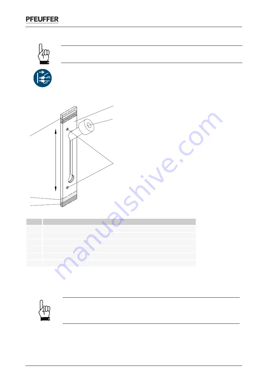
Another adjustment possibility is the detent plate attached to the housing on the left. 


Figure 27: Moving the detent plate 

Item  Designation 

Detent plate 

Pull handle 

Countersinking screw M4 

Mark the initial setting! 

Moving the detent plate upward 

=  lower friability 

Moving the detent plate downward 

=  higher friability 


Use an indelible pen to mark the initial setting of the detent plate. 


Unscrew both countersinking screws. 


Move the detent plate. 


A 3 mm movement corresponds to about 1.5 % friability 
Moving upward = lower friability 
Moving downward = higher friability 


Then tighten the two countersinking screws firmly again. 


Make a note of the movement of the detent plate and the subsequent check with test malt in a test 

log (see master copy on last page). 


4

1

2

3

5
6

Summary of Contents for 1810 0000

Page 1: ...97318 Kitzingen GERMANY Phone 49 9321 9369 0 Fax 49 9321 9369 50 Email info pfeuffer com Revision 7 14 09 2016 Internet http www pfeuffer com Translation of the original operating instructions Operat...

Page 2: ...Copyright This document is not allowed to be communicated or duplicated utilized without express permission which also applies to communicating its content Offenders are liable to the payment of dama...

Page 3: ...maintenance personnel 12 2 3 Safety measures to be carried out by the owner 12 2 4 General safety notes 13 2 5 Safety tests 14 2 6 Residual dangers in connection with the FRIABILIMETER 14 2 7 Switch...

Page 4: ...ings 27 Timer runtime 27 8 1 Abrasion on the pressure roll 27 8 2 Abrasion on the drive rolls 28 8 3 Sieve drum 28 8 4 Precise adjustment using the setscrew 29 8 5 Adjustment by moving the detent plat...

Page 5: ...ersion of the FRIABILIMETER without written consultation with Pfeuffer GmbH is regarded as not in accordance with the designated use Pfeuffer GmbH will not be liable for any damage resulting from this...

Page 6: ...sessment and risk reduction DIN EN 60204 1 2006 Safety of machinery Electrical equipment of machines Part 1 General requirements DIN EN 61010 1 2011 Safety requirements for electrical equipment for me...

Page 7: ...failure to comply Measure to guard against the danger DANGER This is a warning about a highly dangerous situation that will lead to serious or fatal injuries WARNING This is a warning about a dangerou...

Page 8: ...L3 Outer conductor 3 GY N Neutral conductor BU PE Protective earth conductor GNYE Identification 1 6 The information in these operating instructions applies exclusively to the device with the type de...

Page 9: ...ction check M Measurement 2 1 1 Mains disconnector in a portable device The main switch ON OFF is the mains disconnector and also serves as the EMERGENCY OFF function It is located on the top of the d...

Page 10: ...to prevent reaching into the machine CAUTION Danger of crushing Finger injuries During operation do not place your fingers into the filling funnel into the working area of the sieve drum from below NO...

Page 11: ...the front hood is removed during operation Figure 3 Safety device blue magnet for front hood Test Interval Method m V Operating and danger areas on the FRIABILIMETER 2 2 Operating area Make sure the i...

Page 12: ...he owner 2 4 It should be noted that the owner is responsible for the following aspects with regard to the operating and maintenance personnel Providing instruction in the protective devices for the F...

Page 13: ...ng agents and disposal Hazardous substances in Germany the technical rules for hazardous substances TRGS 555 apply Environmental protection regulations Electrical connections The FRIABILIMETER is only...

Page 14: ...sures have been tested Residual dangers in connection with the FRIABILIMETER 2 7 During all work on electrically operated components pay attention to dangers from electrical current Switch off procedu...

Page 15: ...oltage frequency 230 VAC 50 Hz Power consumption 70 VA Number of phases 1 ph PE Protective earth conductor PE yellow green in the mains cable Internal fuse 315 mA slow blow glass microfuse 5 x 20 mm M...

Page 16: ...1 Transport and packaging 4 2 Systems machines and devices from Pfeuffer GmbH are carefully tested and packaged prior to dispatch however it is not possible to exclude the risk of damage during transp...

Page 17: ...nditions and any information indicated on the packaging material Unpacking Open the packaging to avoid damage to the housing and other components Figure 4 Unpacking I Remove the sieve drum the operati...

Page 18: ...ommissioning chapter is only intended for specialist operators Installation 5 1 Carefully unpack the FRIABILIMETER see chapter 4 4 Place the FRIABILIMETER horizontally on a solid table with a smooth c...

Page 19: ...nical abrasion process Weigh out a cleaned sample of 50 g on a balance with 0 01 g accuracy and fill the sample Pull the pull handle and engage it in the bottom position Press the start key The pressu...

Page 20: ...emoves the pressure 7 1 3 Setscrew The setscrew is required for precise adjustment of the FRIABILIMETER see chapter 8 5 7 1 4 Start key The start key starts the investigation The On LED goes out and t...

Page 21: ...t A high husk content or husks which have absorbed water can lead to deviations in the results Malts from particular winter barleys can lead to different results because of their high proportion of hu...

Page 22: ...g of the front hood Insert the plastic funnel into the filler opening on the top Fill the sample NOTE The FRIABILIMETER has a safety circuit The devices switches off immediately when the front hood is...

Page 23: ...ring operation do not place your fingers into the filling funnel into the working area of the sieve drum from below NOTE To avoid damage Make sure that no objects are lying on the device which could d...

Page 24: ...um to collect any particles that may fall out Figure 17 Removing the sieve drum Use the thumb of your left hand to press in the brass roller Lift up the sieve drum with your right hand Pull off the si...

Page 25: ...20 Fractions following the investigation Two fractions are available following the investigation Content of the sieve drum glassy constituents mass A Content of the collecting tray friable constituen...

Page 26: ...he fraction remaining on the sorting sieve in grams Standard values4 Friability bright malt M Whole hyaline WH More than 81 Very good Less than 1 Very good 78 to 81 Good 1 to 2 Good 75 to 78 Satisfact...

Page 27: ...malt approx 80 friability Always store the test malt so the original moisture 3 5 to 5 is retained If the friability results do not match check the following points Before each check of the device set...

Page 28: ...4 Figure 25 Damaged sieve drum Regularly look and check the sieve drum There should not be any tears in the wire mesh or any cracks in the weld Renew the sieve drum if it is damaged For spare parts s...

Page 29: ...pring travel and thus on the force exerted on the sieve drum by the pressure roll Figure 26 Setscrew Item Designation 1 Plastic cap setscrew 2 Pull handle Remove the plastic cap Engage the pull handle...

Page 30: ...late Item Designation 1 Detent plate 2 Pull handle 3 Countersinking screw M4 4 Mark the initial setting 5 Moving the detent plate upward lower friability 6 Moving the detent plate downward higher fria...

Page 31: ...t regular intervals DANGER Touching live parts can be fatal It is essential to comply with the switch off procedure before cleaning maintenance or repair work See chapter 2 8 During all work that is r...

Page 32: ...ter each investigation Drive rolls Use the small or large brush supplied with the product After each investigation Inspection interval and function test 9 2 Sub assembly Interval in one shift working...

Page 33: ...l flat blade screwdriver Figure 29 Pulling out the pressure roll Pull out the worn pressure roll Figure 30 Place spacer rings onto the axle Use the two spacer rings from the old axle with the new pres...

Page 34: ...es Burns to hands and fingers The motor temperature increases during operation reaching in excess of 40 C Allow the FRIABILIMETER motor to cool down adequately after operation or wear protective glove...

Page 35: ...ructions in chapter 9 5 Disconnect the mains cable from the electrical power supply or pull out the coupler Take off the front hood and the sieve drum Figure 31 Opening the housing Item Designation It...

Page 36: ...untersinking screws M4 with a Phillips screwdriver Pay attention to the installation position of the two upper serrated washers Carefully tilt the front plate forward Figure 33 Disconnecting the motor...

Page 37: ...hould be about 0 8 mm The gap B between the front plate and the right drive roll should be about 0 3 to 0 5 mm The distance is set by adding 2 3 shims 6 x 0 3 mm For gaps see Figure 39 Left or right d...

Page 38: ...crews Pay attention to the correct installation position of the two upper serrated washers see Figure 31 Screw the pull handle in firmly Insert the sieve drum and put on the front hood After renewal o...

Page 39: ...Designation Item Designation 1 Fillister head screw 2 9 x 32 mm 4 Timer cover 2 Reed switch 5 Timer bottom part 3 Feeder cable to Reed switch 6 Timer electrical power supply Unscrew the four filliste...

Page 40: ...nnection terminal position A and the two screws on the connection terminal position C Pull off the cables Connect the cables to the new timer as shown in Figure 43 Close the cover Screw the timer onto...

Page 41: ...a Phillips screwdriver Pay attention to the installation position of the two upper serrated washers Carefully tilt the front plate forward Use your thumb and forefinger to press the sides of the motor...

Page 42: ...orrect installation position of the two upper serrated washers see Figure 31 Screw the pull handle in firmly Insert the sieve drum and put on the front hood After renewal of the drive rolls check the...

Page 43: ...ltage Main switch ON OFF is in position OFF Internal fuse in the mains switch defective Have the mains voltage checked by an electrician and switched on Set the main switch to position ON Test and rep...

Page 44: ...is incorrect Renew the sieve drum Check the diameter of the rolls see chapters 8 2 and 8 3 Calibrate see chapters 8 5 and 8 6 Renew worn parts see chapters 9 4 and 9 5 1 Check the runtime with a stop...

Page 45: ...e main switch and disconnect the mains plug from the electrical power supply Pull out the plug connection under the C19 C20 coupler socket Renew the glass microfuse Article number see chapter 11 Inser...

Page 46: ...nstrument 1810 0000 Mains cable with removable connection C19 C20 coupler 2290 0100 Glass microfuse 315 mA slow blow 5x20 mm 10x 3253 0210 Measuring caliper 5400 8100 Can of Pfeuffer GmbH test malt 40...

Page 47: ...CA EBC 4th edition 1987 supplement 1989 Z rich chapter 4 15 Friability and hyaline latest version September 1997 Technical Committee and Editorial Committee of the ASBC 6 8th edition 1988 St Paul Minn...

Page 48: ...ice 8 2 Pressure roll Measured 39 5 mm 39 5 to 39 0 mm 39 0 mm Result OK Recalibrate Renew 8 3 Drive roll Visible abrasion None Slight Severe Not applicable Measure OK Measure Renew Drive roll Measure...

Reviews: