


Adjustment
86
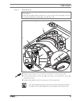
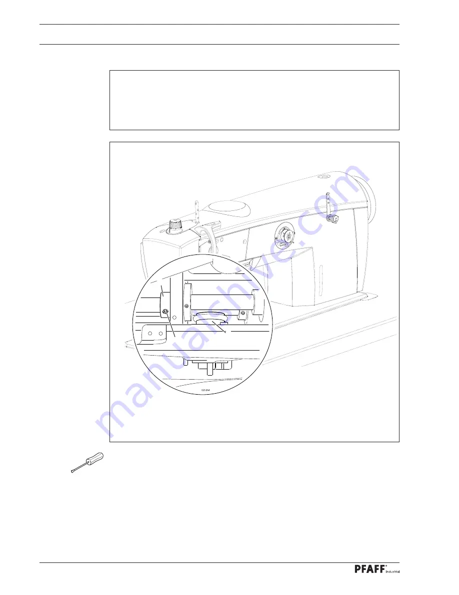
Fig. 4 - 10
4
.05.10
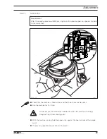
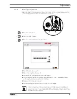
Bobbin winder
Requirement
1. When the bobbin winder is engaged, the winding spindle must be driven reliably.
When it is disengaged, friction wheel
3
should not be touching drive wheel
1
.
2. When it is switched off, the bobbin winder must click securely into its end position
(knife raised).
●
Adjust drive wheel
1
(screw
2
) in accordance with the
requirement
.
2
1
3
Summary of Contents for POWERLINE 3741
Page 1: ...296 12 19 008 002 Betriebsanleitung engl 06 12 DOKU SEAM SYSTEM 3741 3745 ...
Page 7: ...Register 01 ...
Page 8: ......
Page 14: ......
Page 15: ...Register 02 ...
Page 16: ......
Page 43: ...Register 03 ...
Page 44: ......
Page 81: ...Register 04 ...
Page 82: ......
Page 126: ......
Page 127: ...Register 05 ...
Page 128: ......
Page 129: ...Kalibrieranleitung engl 06 12 CALIBRATION INSTRUCTIONS 3741 3745 ...
Page 139: ...Register 06 ...
Page 140: ......
Page 147: ...135 91 191 528 95 Part 1 Version 12 01 12 Circut diagrams ...
Page 148: ...136 Circut diagrams Version 12 01 12 91 191 528 95 Part 2 ...
Page 149: ...137 91 191 528 95 Part 3 Version 12 01 12 Circut diagrams ...
Page 150: ...138 Circut diagrams Version 12 01 12 91 191 528 95 Part 4 ...
Page 151: ...139 91 191 528 95 Part 5 Version 12 01 12 Circut diagrams ...
Page 152: ...140 Circut diagrams Version 12 01 12 91 191 528 95 Part 6 ...
Page 153: ...141 91 191 528 95 Part 7 Version 12 01 12 Circut diagrams ...
Page 154: ...142 Circut diagrams Version 05 01 12 91 191 536 95 ...
Page 155: ...143 91 191 536 95 Version 12 01 12 Circut diagrams ...