background image

5. USE  


5.1 Checks before use  

 
The following precautions must be taken each time before using the machine:  
-  Check that the work surface is free of waste materials and cuttings.  
-  Check the state of the milling cutters before each use of the machine:  
WORN MILLING CUTTERS. Sharpen or replace, following the procedure described in chapter 
MAINTENANCE – section 8.3 – REPLACEMENT OF MILLING CUTTER PACKS.  
MILLING CUTTERS WITH MISSING TEETH. Replace.  
- Check that the pressure on the gauge reads 8 (bar/atm)  
- Check the electrical connection of the plug to the interlocked socket. 
- Check that the emergency button (PE) is not engaged.  
 

5.2 Description of controls  

 
Electric controls and signals:  
 
SIGNALLING LIGHT indicating that the POWER IS ON 

(DWG. A1.18)


When this signalling lamp is on, means that the machine is energised (main switch turned to 
position “1”).  
 
EMERGENCY SIGNALLING LIGHT 

(DWG. A1.18)


When this signalling light is on, it means that the machine is in emergency conditions.  
Verify then, that the emergency push button is not engaged and that the pneumatic circuit is 
powered with enough pressure.  
 
KEY SELECTOR SWITCH FOR PROGRAMMING 

(DWG. A1.18)


This key selector switch is used during the setting phase of the automatic recognition.  
The key must be kept by the personnel responsible for maintenance.  
 
RESET PUSH BUTTON 

(DWG. A1.18) 


This push button is used to come out from the emergency condition. If the red signalling lamp is 
on, check the emergency push button and the air pressure and then act on the RESET push 
button.  
 
EMERGENCY PUSH BUTTON 

(DWG. A1.18)


The push button for the emergency stop is easy recognisable thanks to the characteristic red 
mushroom shape. The push button is of the type with “mechanical hook-up“: to bring it back to 
working conditions pull the mushroom in the operator’s direction. 


MANUALE  D’ISTRUZIONE PER L’USO E LA 
MANUTENZIONE PULITRICE AUTOMATICA CM4S  


24


File: 2240.doc - 03/11/03 14:27 

Summary of Contents for CM4/S

Page 1: ... O BOX 196 50052 CERTALDO FI ITALY TEL 39 0571 651204 FAX 39 0571 652991 e mail pertici pertici it http www pertici it Ver 2 0 MANUALE D ISTRUZIONE PER L USO E LA MANUTENZIONE PULITRICE AUTOMATICA CM4S 1 File 2240 doc 03 11 03 14 27 ...

Page 2: ... the exhaust system 22 5 USE 24 5 1 Checks before use 24 5 2 Description of controls 24 5 3 Operating cycle 26 5 4 Emergency device 27 5 5 Functionality of sensors 27 5 5 1 Microswitches for holding shoulders 27 5 5 2 Microswitches for safety of the locking plate 28 5 5 3 Reed sensors 29 5 5 4 Resistive linear transducers 29 5 6 Precautions to ensure safety during use 29 6 ADJUSTMENTS FOR TOOLS OP...

Page 3: ...nifes for welding seal removal 41 9 SPARE PARTS 42 10 LIST OF ENCLOSURES TO THE INSTRUCTION MANUAL 43 ENCLOSURE 1 44 ENCLOSURE 2 45 ENCLOSURE 3 48 ENCLOSURE 4 51 ENCLOSURE 5 53 ENCLOSURE 6 54 ENCLOSURE 7 55 ENCLOSURE 8 56 MANUALE D ISTRUZIONE PER L USO E LA MANUTENZIONE PULITRICE AUTOMATICA CM4S 3 File 2240 doc 03 11 03 14 27 ...

Page 4: ...o keep the manual in its holder in a safe place near the machine to facilitate future consultation as and when required To make the manual easier to follow reference is made to diagrams from the enclosures The general reference is DWG Ax y whereby A indicates that the diagram is from an enclosure x indicates the number of the enclosure y indicates the page number of the enclosure MANUALE D ISTRUZI...

Page 5: ... the perfect working order of the machine rests entirely with the user if it is repaired or maintained incorrectly by non specialist or unauthorised personnel 2 7 In particular maintenance work on the electrical equipment must be performed by specialist or authorised personnel using original spare parts The machine must be disconnected from the electrical power supply before performing any of thes...

Page 6: ...e the upper and lower welding seals Automatic device for frame positioning Automatic device to start the working cycle Working cycle controlled by an electronic unit PLC Independent adjustment of the milling polishing depth on the external side of the angle Low pressure safety device for frame locking Possibility to modify the working cycle excluding some machining 3 1 Description of the machine A...

Page 7: ...tioning group Dwg A1 2 It is composed of a sheet structure connected to the holding frame on which have been fixed brushes with short and hard bristles turned upwards which permit to support the frame to be processed at the same height of the reference horizontal surfaces for working on the load bearing frame and on which have been fixed the reference shoulders which permit to obtain the proper fr...

Page 8: ...eumatic actuator for the forward movement of the cutter s packs and the actuator for the movement of the lower cutting device The pneumatic actuators for lifting permit the vertical positioning of the 4 cutter groups the pneumatic actuator for the forward movement permit the movement of the cutter s packs in the frame direction to allow the external milling polishing processing At the same time th...

Page 9: ...re for the operator s safety and then at a high pressure for the machining It works also as a support for the upper cutting device for welding seal removal and for the automatic profile recognition optional On this structure are assembled the pneumatic actuators for the vertical blocking the pneumatic actuator for the forward movement of the upper cutting device and if the above mentioned optional...

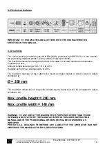
Page 10: ...imum diameter of the cutter to be mount on these models in order to work in safety conditions is Ø 250 mm The maximum dimensions of the profile composing the frame that can be processed in safety conditions are Max profile height 200 mm Max profile width 140 mm WARNING ANY USE OF THE MACHINE FOR PURPOSES OTHER THAN THOSE INTENDED AND STATED BY THE MANUFACTURER IN THIS USER INSTRUCTION MANUAL AND I...

Page 11: ...hree phase unit standard 2 bags KW 1 5 with accessories Device for the automatic turning on of exhaust unit Set of milling cutters by sample 3 6 Tools to be used To execute the corner cleaning the CM4 S uses two types of tools Packs of milling cutters Knifes for welding seal removal 3 6 1 Groups of milling cutters This tool is used to remove the welding seal from the frame external angle The milli...

Page 12: ...efers to the milling cutter which has to polish the profile part in contact with the holding shoulders Starting from the base diameter of the milling cutters act as follows to calculate the diameter of the other milling cutters Examining a straight profile piece measure the distance from the surface resting on the shoulders and the other surfaces to be polished Multiply each measure by 2 to calcul...

Page 13: ...ng cutter has a diameter of Ø 32 G7 tolerance 0 009 0 034 3 6 8 Balancing of milling cutter packs Before using a milling cutter pack it is very important to check its balancing The milling cutter pack at the rotating speed of 3000 rounds per minute must not operate a transversal force greater than 1 gram force ATTENTION THE USE OF NOT BALANCED MILLING CUTTER PACKS INVOLVES DAMAGES TO THE BEARINGS ...

Page 14: ... 89 392 and following modifications Machine directive EEC STANDARD 89 336 and following modifications Electromagnetic Compatibility The following standards and technical specifications have been used D P R N 547 27 4 1955 EN 60240 1 standards September 1993 IEC 44 5 IInd edition EN 292 1 1991 and UNI EN 292 part 1 standards EN 292 2 1991 UNI EN 292 part 2 standards EN 50081 1 1992 standards EN 500...

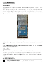
Page 15: ... the crate itself Take great care when performing these operations in order to avoid injury to persons and damage to the machine or property 4 2 Positioning The machine must be positioned on a stable floor Do not install the machine near to areas containing gas or flammable substances as the sparks and glowing fragments produced and scattered may cause explosions or fires Position the machine in a...

Page 16: ...er part of the base plate DWG A1 8 DWG A1 8 Before placing the machine definitely on the floor it is necessary to mount the four vibration damping feet supplied together with the machine Avoid knocks jolts and sudden movements when handling the machine PERTICI SPA declines all liability for damages caused during shipment It is therefore important to check the state of the packaging at the time of ...

Page 17: ...l for normal operations and for inspection and maintenance works The space required to work correctly is of 150 cm all around the machine In the following picture are indicated the safety areas around the machine where the utmost care must be taken to people or objects which may constitute obstacles or hazards during work DWG A1 9 DWG A1 9 MANUALE D ISTRUZIONE PER L USO E LA MANUTENZIONE PULITRICE...

Page 18: ... supplied with the machine DWG A1 10 The support surface of this machine model is wide enough to ensure a good stability and to avoid the machine tilting The machine does not need therefore a permanent anchoring to the floor After placing and levelling remove the blocking elements wooden details of the moving parts of the machine that have been placed to carry out the transport and moving operatio...

Page 19: ...t 7 DWG A1 14 using the 24 mm key supplied Do not lock the nut completely but screw it enough to remove the clearance between the arm and the support in order to allow the rotation of the same arm The height adjustment of the arm is carried out during the machine mounting phase Anyway it is always better to proceed with a check in the following way carry out a working cycle to block a frame on the...

Page 20: ...e working pressure of the user s net must be with full load not less than 8 bar atm Hook up the line to the slide valve mounted on the FRL air treatment unit and check by moving the black collar that the pressure on the gauge reads 8 bar atm If necessary turn the knob on the FRL air treatment unit DWG A1 19 to bring the pressure to the indicated level MANUALE D ISTRUZIONE PER L USO E LA MANUTENZIO...

Page 21: ...und circuit a protective device installed upstream of the machine that is set in such a way as to guarantee the automatic breaking of the circuit in accordance with the above stated specifications We recommend hooking up with an EEC standard interlocked plug and socket with safety fuses of suitable capacity for the machine power input see rating plate We recommend the use of fuses suitable for the...

Page 22: ... 7 Connection to the exhaust system An electrically independent exhausting device can be connected to the machine In case the machine is supplied with the optional Device for automatic starting of exhauster this can be connected directly to the electric socket arranged on the machine DWG A1 16 DWG A1 17 MANUALE D ISTRUZIONE PER L USO E LA MANUTENZIONE PULITRICE AUTOMATICA CM4S 22 File 2240 doc 03 ...

Page 23: ...ter 115 mm suitable to be connected to a Øi 120 mm tube DWG A1 17 Attention the PERTICI SPA supplies upon request optional an exhausting device with 2 bags a power of KW 1 5 an exhausting mouth with a diameter of 200 mm complete with the connection accessories Should the final customer refuse the supply of this optional PERTICI SPA recommends the use of an exhausting device with at least the same ...

Page 24: ...NALLING LIGHT DWG A1 18 When this signalling light is on it means that the machine is in emergency conditions Verify then that the emergency push button is not engaged and that the pneumatic circuit is powered with enough pressure KEY SELECTOR SWITCH FOR PROGRAMMING DWG A1 18 This key selector switch is used during the setting phase of the automatic recognition The key must be kept by the personne...

Page 25: ...tor filter group pushing the collar towards the group the machine is energised moving it in the opposite direction the machine is disconnected and the pneumatic circuit is unloaded thus making all cylinders free for the manual movement ADJUSTING KNOB DISCONNECTING SLIDE VALVE DWG A1 19 MANUALE D ISTRUZIONE PER L USO E LA MANUTENZIONE PULITRICE AUTOMATICA CM4S 25 File 2240 doc 03 11 03 14 27 ...

Page 26: ...he lowest 4 Enter the frame with the angles to be polished The machine activates the device for automatic positioning and pushes the window to the holding shoulders Should the angle be not correctly positioned the controller will send an error on the display Press any key to release the device and repeat the cycle 5 If the positioning results correct the machine activates the low pressure vertical...

Page 27: ...oximity of the magnetic elements of the cylinders 3 resistive linear transducer give a different resistance value as the length varies 5 5 1 Microswitches for holding shoulders The holding shoulders shown in the figure are used as a reference to position the frame to be polished on the machine DWG A1 20 SM5 SM7 SM6 SM8 DWG A1 20 Each shoulder contains two microswitches Entering the frame the PLC o...

Page 28: ...scribed condition happens it means that the machine has not been activated by chance but a frame to be polished was effectively positioned The positioning of such microswitches has been carried out by the PERTICI company during the official acceptance and is suitable to the greater part of profiles that can be found on the market Should it not be suitable to the profile to be processed see the cha...

Page 29: ...omatically soon after having entered the frame in the machine and the device for automatic centering has brought it into working position ATTENTION EVEN IF THE MACHINE IS PROVIDED WITH A LOW PRESSURE SAFETY DEVICE ON THE INTERLOCK DURING THIS OPERATION THE OPERATOR MUST TAKE GREAT CARE FOR THE POSITION OF HIS HANDS ON THE FRAME DURING THE INSERTION IN THE MACHINE The machine is completely protecte...

Page 30: ...top otherwise observe the following indications valid for groups 1 and 2 and 4 1 Turn the machine on and act on key RESET The display shows F1 UPP CUT DEV ON F2 LOW CUT DEV ON F3 MILL CUTT MAN SET MILL CUT 1 2 In case the milling cutter has been set to AUTO or to OFF act many times on F3 to enter MAN 3 Press 3 to enter the position of the third milling cutter 4 Enter an angle to be polished and wa...

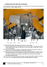
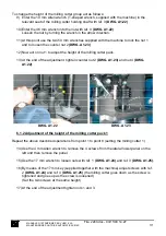
Page 31: ...and nut 4 DWG A1 22 DWG A1 22 DWG A1 23 6 1 2 Adjustment of the height of the milling cutter pack 1 Repeat the above described operations from point 1 to point 8 setting the milling cutter 1 14 Use the 4 mm Allen wrench to remove the 4 screws from the lateral lower panel on the left and then remove the panel 15 Use the 17 mm wrench to loosen nuts with ref 1 DWG A1 24 and ref 3 DWG A1 25 16 By mean...

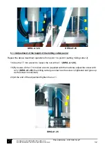
Page 32: ...loosen the nut with ref 1 DWG A1 26 19 By means of the 17 mm Allen wrench supplied with the machine adjust the screw with ref 2 DWG A1 26 the milling cutter goes down as the screw is tightened and goes up as the screw is loosened 20 At the end of the adjustment tighten the nut 1 DWG A1 26 MANUALE D ISTRUZIONE PER L USO E LA MANUTENZIONE PULITRICE AUTOMATICA CM4S 32 File 2240 doc 03 11 03 14 27 ...

Page 33: ...ning machine type CM4 S has a device permitting to adjust the milling depth independently for each single milling cutter group DWG A1 28 The machine is regulated by PERTICI SPA in such a way that the 80 mm guide disc has a milling depth of 2 mm with respect to the theoretical angle root whose two external surfaces rest on the positioning shoulders In the following pages we indicate the 4 screws to...

Page 34: ...to position 0 to remove power from the machine act on the disconnecting valve to cut the air off from the pneumatic equipment Upper knife open the upper right lateral panel DWG A1 1 and move the support of the upper knife manually in the direction of the milling pack groups partially loosen the nut 1 DWG A1 29 and carry out the regulation by turning the screw 2 DWG A1 29 By turning it clockwise th...

Page 35: ... and carry out the regulation by turning the screw 2 DWG A1 30 By turning it clockwise the working depth diminishes while by turning it counter clockwise the working depth increases screw the nut completely 1 DWG A1 30 to fix the adjustment that has been carried out 2 1 DWG A1 30 MANUALE D ISTRUZIONE PER L USO E LA MANUTENZIONE PULITRICE AUTOMATICA CM4S 35 File 2240 doc 03 11 03 14 27 ...

Page 36: ...ished following the positioning example of the following figure The machine blocks the angle 4 The display shows POSITION LIMIT SW 14 15 16 1 1 1 1998 3008 PRESS ANY KEY Open the lateral right door and move the limit switches SM14 15 and 16 DWG A1 21 so that only 15 and 16 will be pressed see the example in the figure On the third line of the display appears the status of each limit switch sensor ...

Page 37: ...cquisition cycle from point 1 to point 5 for all profiles to be processed adjusting the limit switch sensors In case of a wrong acquisition cycle it is possible to cancel it from the memory 6 4 1 Modification of the data for the automatic recognition To modify the data acquired from the previously described programming procedure or to cancel them act as follows 1 From the main menu enter the key s...

Page 38: ...rective 89 392 Encl I Article 1 7 4 point f with measurements made in accordance with ISO 3746 standards The test conditions and results are given in the enclosure 7 of this instruction manual The operator is advised to use protective equipment such as good quality soundproofed ear guards To prevent the exposure level from increasing beyond the test values over time check the sharpening status of ...

Page 39: ...y lead Check the condense level in the collecting container of the FR filter unit should it be high unload the container by means of the relevant valve placed under it 8 2 Extraordinary maintenance weekly Verify the state of wear of the milling cutters Blow whit compressed air to remove dust and scraps if any from the motor safety grid Verify the safety of the electric equipment a isolation of cab...

Page 40: ...he milling cutter packs and mount the rear carter again 8 Loosen levers 3 to let the upper plate go down 9 Tighten knobs 4 and 5 10 Act on key Start the controller displays POSIT 1 MIL CUT N 1 POSIT 2 MIL CUT N 2 POSIT 3 MIL CUT N 3 POSIT 4 MIL CUT N 4 Should it be necessary to install the milling cutter No 5 on position 1 you just have to bring the cursor onto the first line and press key 5 The c...

Page 41: ...g seal removal turn the main switch to position 0 and disconnect the pneumatic equipment by acting on the disconnecting valve Upper knife 1 DWG A1 33 open the right openable panel DWG A1 1 and manually move the upper knife support towards the milling packs Loosen the headless screw 2 DWG A1 33 using the 4 mm hexagonal key supplied 2 1 DWG A1 33 MANUALE D ISTRUZIONE PER L USO E LA MANUTENZIONE PULI...

Page 42: ... DWG A1 34 using the 4 mm hexagonal key supplied 1 2 DWG A1 34 9 SPARE PARTS For the coding and identification of the various components to be considered as spare parts refer to all the technical drawings attached to this manual and to the relevant lists MANUALE D ISTRUZIONE PER L USO E LA MANUTENZIONE PULITRICE AUTOMATICA CM4S 42 File 2240 doc 03 11 03 14 27 ...

Page 43: ... OF CONTENTS A2 0 3 ELECTRIC EQUIPMENT TABLE OF CONTENTS A3 1 4 PNEUMATIC EQUIPMENT TABLE OF CONTENTS A4 1 5 DOCUMENTATION OF COMPONENTS TABLE OF CONTENTS A5 1 6 ELECTRICAL TESTS CERTIFICATION A6 1 7 NOISE TESTS CERTIFICATION A7 1 8 TEST SHEET TEST SHEET A8 1 MANUALE D ISTRUZIONE PER L USO E LA MANUTENZIONE PULITRICE AUTOMATICA CM4S 43 File 2240 doc 03 11 03 14 27 ...

Page 44: ...ACING SHOULDER W MICROSWITCHES TO ACTIVATE THE CYCLE MICROSWITCHES FOR THE LOCKING PLATE ADJUSTMENT OF THE HEIGHT OF MILLING CUTTER PACK 3 ADJUSTMENT OF THE HEIGHT OF MILLING CUTTER PACK 3 ADJUSTMENT OF THE HEIGHT OF MILLING CUTTER PACK 1 ADJUSTMENT OF THE HEIGHT OF MILLING CUTTER PACK 1 ADJUSTMENT OF THE HEIGHT OF MILLING CUTTER PACK 2 ADJUSTMENT OF THE HEIGHT OF MILLING CUTTER PACK 4 ADJUSTMENT ...

Page 45: ...NICHE TABLE OF CONTEST INTRODUCTION LIST OF DRAWINGS EXPLODED DRAWINGS LIST OF COMPONENTS OF PREVIOUS DRAWING A2 0 A2 1 A2 2 A2 3 A2 4 MANUALE D ISTRUZIONE PER L USO E LA MANUTENZIONE PULITRICE AUTOMATICA CM4S 45 File 2240 doc 03 11 03 14 27 ...

Page 46: ... you just have to indicate the code number THE LIST OF MECHANICAL COMPONENTS IS SET OUT AS FOLLOWS MACCHINE TIPO DESCRIPTION OF MACHINE TYPE DWG DRAWING REFERENCE NUMBER POS POSITION DESCRIZIONE DESCRIPTION OF COMPONENTS CODICE PERTICI CODE MACCHINE TIPO This permits to know to which machine type a list refers DWG Reference number linking a mechanical part list to a specific exploded drawing POS I...

Page 47: ...OSITIONING GROUP A2 5 GROUP FOR LIFTING AND FORWARD MOVEMENT OF CUTTER S PACK AND LOWER CUTTING DEVICE A2 6 MOTOR AND MILLING CUTTER PACK HOLDING GROUP A2 7 GROUP WITH LOCKING DEVICE AND UPPER CUTTING DEVICE A2 8 TOTAL SAFETY GUARDS FOR MOVING PARTS AND WORKING AREA A2 9 MANUALE D ISTRUZIONE PER L USO E LA MANUTENZIONE PULITRICE AUTOMATICA CM4S 47 File 2240 doc 03 11 03 14 27 ...

Page 48: ...NIVER CM4 S TABLE OF CONTENTS INTRODUCTION DIAGRAM INTERNAL LAYOUT OF ELECTRIC CABINET LIST OF DETAILS A3 1 A3 2 A3 4 A3 18 A3 19 MANUALE D ISTRUZIONE PER L USO E LA MANUTENZIONE PULITRICE AUTOMATICA CM4S 48 File 2240 doc 03 11 03 14 27 ...

Page 49: ...top left The reference Drwg A3 4 q1indicates that the conductor continues from drawing A3 4 at co ordinates q1 top right The connectors used are illustrated in the diagrams together with the corresponding connector number C 2 and position of the conductor inside 12 C 2 12 LIST OF ELECTRIC COMPONENTS THE LIST OF ELECTRIC COMPONENTS IS SET OUT AS FOLLOWS RIF REFERENCE TAV DRAWING DESCRIZIONE MATERIA...

Page 50: ...e electrical system NUM This column indicates the number of pieces of the component TIPO In This column indicates the type of component the fuse current or the manufacturer s article number in order to facilitate the independent purchase of said part or identification of its specifications in the supplier s catalogue FORNITORE This column indicates the component supplier NS CODICE This column indi...

Page 51: ...EQUIPMENT TABLE OF CONTENTS A4 1 INTRODUCTION A4 2 FUNCTIONAL DIAGRAM A4 3 DIAGRAM OF CONNECTIONS AND COMPONENTS A4 4 MANUALE D ISTRUZIONE PER L USO E LA MANUTENZIONE PULITRICE AUTOMATICA CM4S 51 File 2240 doc 03 11 03 14 27 ...

Page 52: ...s set out as follows RIF REFERENCE Components and connections are listed in this column in alphanumerical order while the pipes are listed according to their diameter PAG PAGE In this column are given the pages where the component is used and the page on which it is physically represented in order to facilitate its finding and if necessary its replacing DESCRIZIONE A short description of the compo...

Page 53: ...F COMPONENTS TABLE OF CONTENTS EXPL DRAWING OF CYLINDERS EXPL DRAWING OF MOTOR EXPL DRAWING OF REDUCER A5 1 A5 2 A5 3 A5 4 MANUALE D ISTRUZIONE PER L USO E LA MANUTENZIONE PULITRICE AUTOMATICA CM4S 53 File 2240 doc 03 11 03 14 27 ...

Page 54: ...d ELECTROMAGNETIC COMPATIBILITY Passed FUNCTIONAL TESTS Passed CONSUMPTION WITHOUT LOAD VOLT 400 HZ 50 2 1 A CONSUMPTION WITH LOAD VOLT 400 HZ 50 2 7 A The test conditions and instruments used are described in the TECHNICAL BROCHURE referring to this manual MANUALE D ISTRUZIONE PER L USO E LA MANUTENZIONE PULITRICE AUTOMATICA CM4S 54 File 2240 doc 03 11 03 14 27 ...

Page 55: ...46 standard and to the use of the R40 profile of the firm Metra for a cutting length of 2000 mm SOUND LEVELS ACCORDING TO THE ISO 3746 STANDARD The results shown in the tables below were obtained from the tests performed AVERAGE ACOUSTIC PRESSURE LEVEL IN THE ATMOSPHERE CM4 S LpAm dB A 78 8 ACOUSTIC POWER LEVEL CM4 S LwA dB A 108 4 ACOUSTIC PRESSURE LEVEL AT OPERATOR STATION CM4 S LpAm dB A 81 2 T...

Page 56: ...MANUALE D ISTRUZIONE PER L USO E LA MANUTENZIONE PULITRICE AUTOMATICA CM4S File 2240 doc 03 11 03 14 27 56 ENCLOSURE 8 TEST SHEET ...

Reviews: