background image

Chairman Robo Owner´s manual

General introduction

- 8 -

General introduction

In  order  that  you  can  obtain  the  greatest  possible  benefit  from  the  chair,  it  is
important that it is used in the intended manner. We would, therefore, like you to
read the Owner’s Manual carefully, in particular the safety instructions. Keep the
Owner’s Manual together with everything else associated with your wheelchair.

The first thing to do is to charge the batteries. Read the chapter Charging the
Batteries on page 30 if you are uncertain about how to do this. Charging takes
approximately 9 hours.

Specially adapted wheelchair

If your wheelchair is marked with the decal "specially adapted product", it has
been adapted to your requirements and wishes. This means that its design and
functions  may  differ  from  the  text  in  the  present  Owner’s  Manual  or  from  the
design and functions of other wheelchairs of the same type..

Specifications

All the information and specifications contained in the present Owner’s Manual
were valid at the time of delivery of this wheelchair. As development and impro-
vement take place continuously at Permobil, we reserve the right to make chan-
ges without prior notification.

Summary of Contents for Chairman Robo

Page 1: ...Owner s manual Chairman Robo US ...

Page 2: ...rmobil Inc USA 6961 Eastgate Blvd Lebanon TN 37090 USA Phone 781 932 9009 Fax 781 932 0428 Head Office of the Permobil group Permobil AB Box 120 861 23 Timrå Sweden Tel 46 60 59 59 00 Fax 46 60 57 52 50 E mail firmapost permobil se ...

Page 3: ... 4 Owner s manual Chairman Robo Produced and published by Permobil AB Sweden Edition no 2 9911 Order no 201106 US 0 PAB no 1106 2 2 ...

Page 4: ... 14 Accessories 21 Tool bag 21 Accessories 22 Handling 23 General 23 Driving 23 Driving rules 26 Releasing the brakes 29 Charging the batteries 30 Transport 33 Air transport 34 Preventive Maintenance 35 General 35 Cleaning 36 Wheels 36 Batteries 36 Lubrication 36 Repairs 37 Changing the fuses 37 Changing the batteries 39 Changing inner tubes 41 Filling with air 41 Changing bulbs 42 Technical speci...

Page 5: ...ons in the vital systems of the wheelchair must be performed by a qualified service engineer Always contact a qualified service engineer in cases of doubt Please show great caution where this warning symbol appears There is a risk of personal injury Passengers The wheelchair is not designed to transport passengers regardless of their age Driving Do not drive the wheelchair over kerbs and other obs...

Page 6: ...hen the charger is connected the chair must not and cannot be driven Transport Ensure that the wheelchair is properly secured see page 33 If the chair is not properly secured and comes loose it can cause serious injury to persons in the vehicle and serious damage to the vehicle Service Carry out only the service and maintenance which are stated in the Instructions for Use All other service and mai...

Page 7: ...page 30 if you are uncertain about how to do this Charging takes approximately 9 hours Specially adapted wheelchair If your wheelchair is marked with the decal specially adapted product it has been adapted to your requirements and wishes This means that its design and functions may differ from the text in the present Owner s Manual or from the design and functions of other wheelchairs of the same ...

Page 8: ... s manual Design and function 9 Design and function General Figure 1 Chairman Robo front view 1 Seat 2 Chassis 3 Drive wheel 4 Control panel 5 Terra unit seat lift 6 Rear wheel 2 1 3 6 Figure 2 Chairman Robo rear view 4 5 ...

Page 9: ... 10 Seat See the supplied Owner s Manual for the seat Seat lift The Chairman Robo is equipped with a unique seat lift system which makes it possible to adjust the height of the seat from 6 1 2 to 28 Figure 3 Highest position Figure 4 Lowest position ...

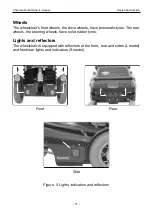
Page 10: ...rive wheels have pneumatic tyres The rear wheels the steering wheels have solid rubber tyres Lights and reflectors The wheelchair is equipped with reflectors at the front rear and sides L model and front rear lights and indicators S model Figure 5 Lights indicators and reflectors Front Rear Side ...

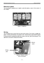
Page 11: ...ric motor Driving gear Figure 6 Batteries Driving The wheelchair has a drive pack for each drive wheel The motors regulate the speed turning and braking A joystick on the manoeuvring panel sends signals to the electronics unit placed under the cover on the rear part of the chassis The electronics unit then controls the motors Figure 7 Electric motor with driving gear ...

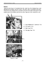
Page 12: ... 24V switched and 24V direct The main fuse is mounted on the elec tronics unit the charging fuse is located on the thin red cable which goes to the positive pole of the battery and the two other fuses are in the electronics unit 1 Seat lift lights 24 V switched 15 A 2 24 V direct 15 A 3 Main fuse 80 A 4 Charging fuse 15 A 3 1 2 4 Figure 8 Fuses ...

Page 13: ...rol Panel The control panel of the wheelchair is mounted on the right arm rest and its loca tion can be adjusted to achieve the most comfortable position in connection with maneuvering The control panel can also be mounted on the left arm rest The figure below shows the various functions of the control panel Figure 9 Chairman Robo S control panel 1 2 3 4 5 6 7 9 8 Not used if there is an additiona...

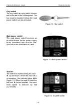
Page 14: ...plug which is inser ted in the side of the control panel The key must be inserted before the main power switch can be activated Figure 10 Key switch Seat lift The switch for maneuvering the seat lift up and down When the seat lift is in operation the indicator lamp lights figure 11 When the seat lift is activa ted from its lowest position the maxi mum speed is reduced by half 2 2 miles h Figure 12...

Page 15: ...miles h Medium 0 2 2 miles h High 0 4 5 miles h Battery voltage indicator The window display on the control panel figure 12 shows the following indications from left to right Red yellow green Fully charged Red yellow Semi charged Red Charge the batteries Figure 13 Battery voltage indicator Horn Pressing this switch produces a sound to attract attention Figure 14 Horn switch Figure 15 Speed selecto...

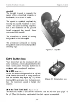
Page 16: ...ly proportional to the movement of the joystick small movement low speed large move ment high speed The wheelchair is turned by moving the joystick to the left or right The wheelchair is braked by moving the joystick back to the neutral position or letting it go Figure 17 Joystick Lights Pressing this switch turns on the wheelchair s lights Indicators Pressing on the right or left arrow activates ...

Page 17: ...t arm rest and its loca tion can be adjusted to achieve the most comfortable position in connection with maneuvering The control panel can also be mounted on the left arm rest The figure below shows the various functions of the control panel 1 2 3 1 Maximum speed control 2 Main power switch warning lamp 3 Joystick Figure 18 L control panel ...

Page 18: ... are On constantly The chair is ready to be driven Flashing slowly once per second Batteries low Charge them as soon as possible Flashing fast twice per second Electrical data battery or motor fault Contact service Maximum speed The maximum speed can be adjusted steplessly using the maximum speed knob Turning it anticlockwise reduces the speed Figure 19 Maximum speed knob Figure 20 Main power swit...

Page 19: ...o the neutral position or letting it go Figure 21 Joystick Extra button box Your wheelchair can be equipped with an extra button box which is located behind the main control panel The extra button box is equipped with a number of functions Seat lift figure 22 1 Switch for maneuvering the seat lift up and down When the seat lift is being maneuve red the indicator lamp lights fig 12 When the seat li...

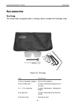
Page 20: ...ns the following tools Figure 23 Tool bag Tool Area of use 1 Pair of protective goggles Work on the batteries 2 Set of Allen keys General maintenance adjustment of the seat 3 1 x 13 mm spanner General maintenance changing the battery 4 Screwdriver General maintenance removing the covers 5 Seat lift crank Raising the seat ...

Page 21: ...ries 22 Accessories Accessories for the Chairman Robo include a rear view mirror joystick in the table central control Contact your nearest Permobil dealer for more detailed information on the acces sories available for the Chairman Robo ...

Page 22: ...wnhill slopes and not to drive over kerbs and other obstacles higher than 2 3 4 Do not make the first test run on your own The test run is to find out how you and the wheelchair work together and you may need some assistance Driving 1 Insert the key switch in the side of the panel only S panel 2 Switch on the power by pressing the main power switch on the control panel Panel S Panel L Figure 24 Ma...

Page 23: ...ackwards to reverse Figure 26 Joystick Panel L Panel S Figure 25 Speed selector 3 Panel S Select a suitable speed range by pressing the speed selector until the desired indicator lamp lights for your type of driving Panel L Select a suitable speed range by turning the maximum speed knob Turning it clockwise increases the speed range turning it anticlockwise reduces the speed range ...

Page 24: ...eed should be set to low speed You can brake gently by pulling the joystick back to a position just before the neutral position When the speed has been reduced you can let the joystick go NB The wheelchair moves at reduced speed if the seat is raised You can only drive at full speed if the seat is in its lowest position Raising the seat lift raises the centre of gravity and increases the risk of t...

Page 25: ...man Robo Owner s Manual Handling 26 Driving rules High kerbs and other obstacles Figure 28 High kerbs and other obstacles Do not drive the wheelchair over kerbs and other obstacles higher than 2 3 4 WARNING ...

Page 26: ... Manual Handling 27 Figure 29 Driving downhill 12 The wheelchair is not designed to be driven down slopes steeper than 12 degrees Downhill slopes When driving downhill you must drive at low speed and take great care WARNING ...

Page 27: ...opes Do not drive the wheelchair along slopes steeper than 10 degrees There is a risk of tipping Driving along slopes Do not drive up slopes steeper than 12 degrees Uphill slopes If you drive up slopes steeper than 12O there is a risk that the wheelchair can not be maneuvered safely WARNING WARNING ...

Page 28: ...can be released to make it possible to move the wheelchair manu ally 1 Switch off the wheelchair by switching off the main power switch 2 Move the lever forwards figure 32 The chair can now be moved manually NB Reset the brakes after moving the chair by pulling the lever backwards When the brake release has been activated the wheelchair cannot be driven Figure 32 Releasing the brakes WARNING ...

Page 29: ...rging the batteries Take care when using metal objects in connection with work on the batte ries Short circuiting can easily cause an explosion Always use protective gloves and goggles Use only chargers with a maximum 10 A charging current mean value The effective value of the charging current must not exceed 12 A Figure 33 Lester Electrical s Dual mode charger WARNING WARNING WARNING ...

Page 30: ...see figure on page 14 The batteries must then be charged as soon as possible If the batteries should become completely discharged it is important that you recharge them as soon as possible If you delay before recharging them the bat teries can be damaged Charging 1 Connect the mains cable to the mains 2 Connect the connection cable from the charger to the charging socket on the wheelchair which is...

Page 31: ...and rear If the chair has to be transported in a van estate car or other vehicle it is extremely important that the chair is secured properly and that the fastening points used are well anchored in the vehicle Figure 35 Rear fastening loops If the chair is not properly secured and comes loose it can cause serious injury to persons in the vehicle and serious damage to the vehicle and itself WARNING...

Page 32: ...ed in special boxes provided by the airline Some airlines refuse to take acid batteries aboard at all so always check with the airline in question which rules apply See page 39 40 for how to remove the batteries The dimensions and weight of the wheelchair The weight and dimensions of the wheelchair are significant in relation to the type of airplanes in which the wheelchair is to be transported Th...

Page 33: ... to look after it Preventive maintenance is intended to prevent faults If you look after your wheelchair it will work well and the risk of faults is reduced Any inappropriate modifications to the wheelchair and its various systems may entail an increased risk of accidents Carefully follow the recommendations in the Handling section to prevent the risk of accidents in connection with driving All mo...

Page 34: ...ion occurs mist or moisture on surfaces i e wash houses or similar rooms The wheelchair may be stored in an unheated room From the point of view of corrosion it is best for the chair if the room is a few degrees warmer than the surroundings which keeps the room drier Short term storage In order for the charging process to produce a battery with good capacity the temperature in the storage room sho...

Page 35: ...orage Please note that batteries discharge of their own accord and that a discharged battery may freeze and burst when it is cold If the wheelchair is to be stored and not used for a long period of time the batteries must always be charged once per month to avoid damaging them NB The temperature in the storage room should not be less than 41 F If your wheelchair is equipped with acid batteries the...

Page 36: ...f the cover Ensure that the rear light cables in the rear cover are firmly connected to the electronics connector Main fuse The main fuse must only be changed by persons with a good knowledge of the wheelchair NB If the main fuse blows there is often a major electrical fault and a service engineer should be called Change the main fuse and refit the rear cover Figure 37 80 A main fuse ...

Page 37: ...The fuse holder for the charging fuse is located on the thin red cable which goes to the positive pole of the battery 1 2 3 Pull the lid off the fuse box Change blown fuses Refit the lid of the fuse box refit the rear cover and screw it in place 1 Seat lift lighting 24 V switched 15 A 2 24 V direct 15 A 3 Jumper Do not remove 4 15 A charging fuse 4 ...

Page 38: ... the cables for the rear lights are fastened to it 4 Loosen the nuts fig 42 two turns pull the guide yoke upwards NB This work is best performed by two people one to loosen the nuts and pull up the guide yoke and another to hold the seat and prevent it from falling If you are working on your own get a good hold of the seat and check that no one is directly in front of the chair before you pull the...

Page 39: ...r an electronics fault has occurred and the seat is not raised the adjustment device for the terra function must be loosened This is done as follows Remove the black plastic plug fig 44 and unscrew and remove the Allen screw Get a good hold on the seat and pull it forwards upwards until the foot plate is resting on the floor Lift off the top cover which is fixed with Velcro The chair is now access...

Page 40: ...in the tyres produces abnormal wear and reduces the range Therefore check regularly that the front tyres have a pressure of 0 2 MPa 2 kp cm2 1 Unscrew and remove the plastic caps on the air valves on the drive wheels 2 Connect the compressed air nozzle to the air valve and adjust the tyre pres sure to the prescribed level The recommended air pressure is 0 2 MPa 2 kp cm2 Overfilling entails the ris...

Page 41: ...t indicators 1 Turn the indicator glass figure 46 2 90O anticlockwise 2 Lift the indicator glass straight up do not screw 3 Change the bulb Figure 46 Front light 2 Figure 47 Rear light Bulbs Socket type Power Headlamps R10 E10 24V 3W Front indicators 13256 24V 3W Rear lights SP36 24V 3W Rear indicators SP36 24V 3W Rear lights and indicators 1 The rear indicator bulb upper bulb and rear light bulb ...

Page 42: ...Chairman Robo Owner s Manual Technical specifikations 43 Technical specifikations ...

Page 43: ... x 7 x 8 1 2 25 x 18 x 21 5 cm Wheels Wheel dimensions front 300 x 8 Air pressure in front wheel 0 2 MPa 2 kp cm2 Wheel dimensions rear 200 x 50 Performance Range 19 24 5 Miles2 30 40 km2 Maximum speed forwards 4 5 miles h 7 5 km h Maximum speed backwards approximately 3 miles h 5 km h Turning circle 180 degrees 40 5 103 cm Maximum height of abstacles 2 3 4 7 cm Maximum slope 12 degrees Maximum us...

Page 44: ...Owner s Manual Technical Specifications 45 Electrical system Batteries Recommended battery type Gel Battery capacity 2 x 73 Ah Charging time 9 hours Fuses Charging fuse 15 A Seatlift 15 A Lighting 15 A Main fuse 80 A ...

Page 45: ...The higher the immunity level the greater the protection At this time requested immunity level as per EN 60601 1 2 is 3 V m The immu nity level of this powered wheelchair model as shipped with no further modifi cation is 20V m in the range of 26 MHz to 950 MHz There are a number of sources of relatively intense electromagnetic fields in the everyday environment Some of these sources are obvious an...

Page 46: ...f the powered wheelchair WARNINGS Electromagnetic interference EMI from sources such as radio ant TV stations amateur radio HAM transmitters two way radios and cellular phones can affect powered wheelchairs and motorised scooters Following the warnings lis ted below should reduced tdhe chance of unintended brake release or powered wheelchair movement wich could result in serious injury 1 Do not op...

Page 47: ...Chairman Robo Owner s Manual Personal notes 48 ...

Page 48: ...Chairman Robo Owner s Manual Personal notes 49 ...

Page 49: ...Chairman Robo Owner s Manual Personal notes 50 ...

Page 50: ......

Reviews: