Model 5210D User’s Manual
Doc. SE-MAN-050 REV 00
Page 12 of 25
©2017 Perma Pure LLC. All rights reserved. Specifications subject to change.
BASIC OPERATION
Your cooler comes from the factory ready to go, preset to operate at 4°C, and to close the sample pump relays at
10°C. Closing the pump relays illuminates the READY status LED, near the temperature display
.
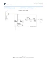
See the
interconnection diagram for a typical installation that includes water slip sensing, using cooler controlled pump
relays, interlock input and alarm relays. Your cooler can be operated without using any of these on-board
features.
CONTROLLER:
This cooler is controlled by a digital control board.
Throughout this manual, channel 1 refers to the left channel when facing the display, and channel 2 to the right.
This board regulates power to the Peltier elements to maintain the set point temperature regardless of the thermal
load on the channel (within the specified ranges). The board is capable of independently controlling two separate
channels. The board provides a pulse width modulated power output to the Peltier elements as determined by a
temperature control loop.
In addition, this board includes fused sample pump relays, alarm relays, 0-3V analog output, New Jersey
thermocouple input and output, and slip sensor electronics.
This controller is digitally controlled and configured using a PC via USB and proprietary software.
THE DISPLAY
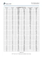
The display operation varies depending on as shipped configuration. When the unit powers on, it will briefly
display R-XX (r-01, r-02, etc.). This is the revision of the control software loaded into the on-board memory.


