Perle IDS-509PP Hardware Installation Manual Download Page 5

IDS-509PP Hardware Installation Guide

                                                                                                                                                                                                                                                                    3

Overview

This chapter discusses the following topics:

Switch Model View
LED Indicators
Ports
Port Status Indicators
Terminal Block Connectors
DIP Switches

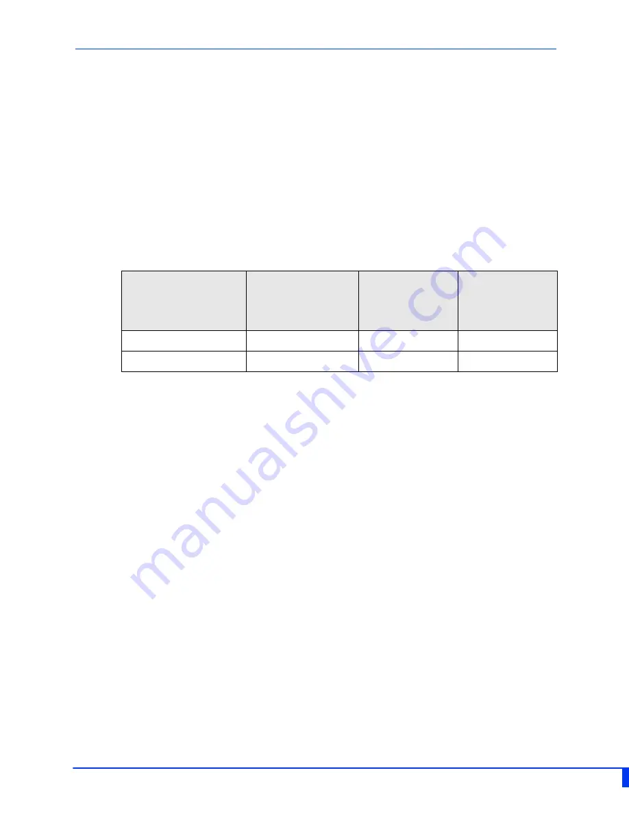
The table below gives a brief overview of the models covered in this guide. For more 
details and for the most up-to-date list of models, please refer to the product pages at 
www.perle.com.

Standard Models

10/100/1000Base-T 
Ethernet Ports 

10/100/1000
Base-T Ports 
Ethernet 

PoE+ Enabled

Temp

IDS-509PP8

1

8

Standard

IDS-509PP8-XT

1

8

Industrial

Summary of Contents for IDS-509PP

Page 1: ...IDS 509PP Hardware Installation Guide PoE Managed Industrial Ethernet Switches Updated November 2017 Version A 11 23 28 2017 Document Part 5500386 10 Rev K www perle com ...

Page 2: ...ference when the equipment is operated in a commercial environment This equipment generates uses and can radiate radio frequency energy and if not installed and used in accordance with this hardware guide may cause harmful interference to radio communications Operation of this equipment in a residential area is likely to cause harmful interference in which case users will be required to correct th...

Page 3: ...IDS switch 11 Connecting Power to the IDS Switch 11 Wiring the Relay Alarm 12 Wiring Digital Inputs 12 Connecting the Console Port 13 Connecting Data Ports 15 Resetting the Switch 15 Configuring the IDS Switch 18 Appendix A Technical Specifications 19 Appendix B Sample Label 23 Appendix C Mechanical Drawings 24 Appendix D DIN Rail and Wall Mounting 25 Appendix E IDS Maintenance 27 Appendix F Cable...

Page 4: ...itch with attached DIN rail mounting bracket Quick Start Guide Document Conventions This document contains the following conventions Most text is presented in the typeface used in this paragraph Other typefaces are used to help you identify certain types of information The other typefaces are Note Means reader take note notes contain helpful suggestions Caution Means reader be careful In this situ...

Page 5: ...lock Connectors DIP Switches The table below gives a brief overview of the models covered in this guide For more details and for the most up to date list of models please refer to the product pages at www perle com Standard Models 10 100 1000Base T Ethernet Ports 10 100 1000 Base T Ports Ethernet PoE Enabled Temp IDS 509PP8 1 8 Standard IDS 509PP8 XT 1 8 Industrial ...

Page 6: ...k for Power 1 2 7 10 100 1000Base T Ethernet Ports with PoE PoE capability 2 Status LEDs 8 SD card slot 3 Console Port serial 9 Terminal Block for Digital Inputs Relays 4 Console Port USB 10 Reset FS 5 DIP switches 11 DIN Rail Clip 6 10 100 1000 Base T Ethernet Port 12 Wall Mount Bracket Screw Holes ...

Page 7: ...ications State Description Green blinking after power on System booting Green solid System ready operating normally Green blinking slowly Fast Setup Mode activated port available Green blinking fast Fast Setup Mode activated no port available Red Hardware fault or firmware load error State Description Off No alarms configured Green solid Alarms configured but no alarms detected Red solid Alarm con...

Page 8: ...Backup Coupling Link enabled State Description Off Ring Master not activated Green solid Ring Master Active redundant port blocked Coupling Link enabled Green flashing Ring Master unable to establish a ring due to missing link on one of the Ring ports Yellow solid Ring Master Active redundant port unblocked indicates a break in the Ring ...

Page 9: ... alternative connection to the switch s console This provides access to the switch management function using the industry standard CLI command set When connected the port presents a serial interface that can be used from a PC Terminal emulation program such as PuTTY Power Connector The power input connector has provisions for dual inputs Two independent power sources can be used to power the switc...

Page 10: ... Power Input 1 P2 Power Input 2 IN 1 Digital Input 1 Dry Contact IN 2 Digital Input 2 Wet Contact R Relay with 2 connection points Normally Open NO Normally Closed NC State Description Green 1000 Mbps Green Yellow 100 Mbps Yellow 10 Mbps On solid Port Link Random blinking Port Link and Activity Slow blinking Error disabled Rapid blinking Port in Fast Setup Mode ...

Page 11: ...d during system boot up If a DIP switch is changed the IDS switch must be rebooted in order for the change to take effect DIP Switch Ring Feature SW1 SW2 Ring Role Coupling Mode Description On On Software control Ring Master functionality is controlled by software configuration On Off Master Primary Ring Feature enabled Ring Role Master Coupling Active on Port 4 Note 1 Off On Client Standby Ring f...

Page 12: ...d for operation with Safety extra low Voltage SELV Connect only to SELV circuits with voltage restrictions in line with IEC EN 60950 1 Hazardous Location Warnings Warning This equipment shall be installed in an enclosure that provides a degree of protection not less then IP54 in accordance with EN 60079 15 and accessible only by the use of a tool Warning The equipment shall only be used in an area...

Page 13: ... surface Terminal Block Power Connectors Grounding the IDS switch If your installation requires additional grounding follow this procedure Grounding the chassis requires the following items One grounding lug not provided One 12AWG wire not provided Follow the manufacturers instructions for attaching the ground wire to the grounding lug Attach the grounding lug to the chassis and secure with the gr...

Page 14: ...e within the stated Alarm Relay specifications Warning In hazardous location installations failure to remove the power from the source prior to completing the wiring connections to the alarm relay could cause an electrical arc resulting in a possible explosion Wiring Digital Inputs The IDS switch has two digital input connections one to sense to Dry Contact and one to sense a Wet Contact IN1 This ...

Page 15: ...See appendixes for console port pinouts Console Ports The console port is an 8 pin female connector with DTE pinouts 1 Connect an RJ45 cable to the IDS switch console port RJ45 and the other end of the cable to a COM port onyour PC 2 Choose Start Control Panel Systems or equivalent on the WindowsOperating System you are using 3 Click the Hardware tab and choose Device Manager Expand the Ports COM ...

Page 16: ... Windows Operating System then open the Hardware tab Choose the Device Manager and expand the Ports section The assigned COM port appears can be identified 4 Start an terminal emulation program such as Putty or SecureCRT on the com port where you have connect the cable to the PC 5 Configure your COM port within the emulation program on the PC as 9600 baud 8 data bits 1 stop bit No parity None flow...

Page 17: ...itch Gigabit Ethernet requires CAT5 orbetter 2 Once the device is connected and link is established the link LEDs will turn on These LEDs willindicate whether you have a 10 100 or 1000 Mb s link to the switch See LED Indicators for moredetails Note It may take a few seconds for the device to become active By default the IDS switch will have Rapid Spanning Tree RSTP protocol enabled This protocol w...

Page 18: ...ton apply power to the switch ALR LED will go on after power up when it goes out release the reset button The switch is now reset to factory default configuration Booting the Switch When first applying power to the IDS switch it will startup and go through the boot pro cess The LEDs will behave according to the table below Fast Setup Mode This allows you to perform initial configuration of the swi...

Page 19: ...t Setup Mode sequence will activate Password recovery Note The password recovery feature can be disabled in the software LED Behavior PWR Press and hold the Reset FS button Release button when LED changes from Red to Yellow Port Link Speed Rapid blinking on the first available RJ 45 port to which the PC can be connected LED Behavior ALR On solid during reset process Off to indicate that reset has ...

Page 20: ... Web Device Manager The Perle Web Device Manager is an embedded Web based application that provides an easy to use browser interface for managing the switch This interface provides the ability to configure and manage the switch This is accessible through any standard desktop web browser Requires the switch to have a valid IP address Fast Setup This utility provides the ability to do either an init...

Page 21: ...al 44 57 VDC PoE 802 3af or IEEE 802 3at type 1 5 5A Max Alarm Relay NO Normally Open NC Normally Closed con tacts 1 0A 24VDC or 0 3A 48VDC Requires Class 2 LPS or SELV circuit with Fuse protection Digital Input IN1 Connects to Dry Contact Circuit Provides 12V 36mA On 2 1mA 4K Ohms Off 1 2mA 9K Ohms Digital Input IN2 Connect to Wet Contact Circuit requires external power Input Voltage Rating 36 to...

Page 22: ...to 100 meters 328 ft Auto negotiation Auto MDI MDIX Ethernet isolation 1500 V Console port RJ45 DTE serial port MicroUSB Type B female port serial interface Switch properties Standards IEEE 802 3 for 10Base T IEEE 802 3u for 100Base TX IEEE 802 3ab for 1000Base T IEEE 802 3x for Flow Control IEEE 802 3at type 2 IEEE 802 3af or IEEE 802 3at type 1 Environmental Specifications Operating Temperature ...

Page 23: ...EC EN 61000 4 2 ESD Contact discharge 4kV Air Discharge 8kV IEC EN 61000 4 3 RS 20Vm 80Mhz 1GHz 10Vm 1 4GHz 2GHz 2GHz 5Vm 2GHz 2 7GHz IEC EN 61000 4 4 EFT DC power line 2kV I O 1kV IEC EN 61000 4 5 Surge DC power line Line Line 1 1kV Line Earth 1 1kV Data Line line earth 1 1kV IEC EN 61000 4 6 CS 150Hz to 80 MHz 10Vrms IEC EN 61000 4 8 Magnetic Field 30 A m EN 61000 6 2 2005 AC 2005 IEC 61000 6 2 ...

Page 24: ...for the Perle Technical Assistance Center PTAC can be found at the link below www perle com support_services support_request shtml Warranty Registration This product is covered by the Perle Ethernet Switches Warranty Details can be found at https www perle com support_services warranty shtml ...

Page 25: ...IDS 509PP Hardware Installation Guide 23 Appendix B Sample Label ...

Page 26: ...IDS 509PP Hardware Installation Guide 24 Appendix C Mechanical Drawings ...

Page 27: ...e DIN rail clip attach onto the top of the DINrail 3 Rotate the bottom of the IDS switch towards the rail This will snap the bottom hooks of the DIN rail cliponto the bottom of the DIN rail Removing the IDS from the DIN Rail 1 The DIN rail attachment clip has a slot at the bottom of the latch that is visible beneath the switch when it is mounted 2 Insert a flat blade screwdriver into the slot and ...

Page 28: ... spot where the screws will beplaced 4 Drive the screws into the wall leaving about 2 mm of the screw protruding from the wall to allow roomfor sliding the wall mount panel between the wall and the screws 5 Once the screws are fixed to the wall insert the four screw heads through the large parts of the keyhole shaped screw openings 6 Pull the IDS switch down to lock the IDS switch to the wall moun...

Page 29: ...2 inches on all sides of the IDS switch to pro vide proper airflowthrough the unit Do not use solvents or cleaning agents on this unit Keep vent holes clear of debris If case gets dirty wipe with a dry cloth Ensure all cables are in good working condition Replace any frayed cables or cables without clips ...

Page 30: ...devices These Ethernet ports will automatically adjust depend ing on the type of Ethernet cable used straight through or cross over and the type of device NIC type or HUB Switch type connected to the port Requirements Cat 5 UTP or STP Cat 5e cables 24 22 AWG 0 20mm2 0 33mm2 Straight through or Ethernet Crossover cable Note An optional cable adapter is available to provide RJ45 to DB9 conversion Pe...

Page 31: ...ces Supports IEEE 802 3af Type 1 and IEEE 802at 2009 Type 2 standards For PoE devices up to 15 4 watts per port For PoE devices up to 30 watts per port Connect the copper cables from each TP port RJ45 on the IDS 509PP switch to compliant Powered Devices PDs See below for RJ 45 pinouts on port 1 8 ...

Reviews: